
Since there are so many things to learn about Orange Beginner Kit for Arduino, we must have a roadway, because without a road we cannot get to the destination.
I know the pain of the self-learning process and talking about me when I started learning Arduino, I faced many issues while learning Arduino.
But in this blog, I have covered everything that I wish I had when I was learning Arduino.
And I believe that these things will help you to understand the concepts of Arduino and moreover, if you face any problem while learning this Arduino kit, you mention your doubts in the comment section and our team Will help you in a proper solution.
So let’s start on the quest to learn new things.
Components List
We are getting the following components with the orange Beginner Kit.
| Sr No. | Components Name | Quantity |
|---|---|---|
| 1. | Arduino Ch340G Uno | 1 |
| 2. | Arduino Uno USB Cable | 1 |
| 3. | Resistor Pack | 1 |
| 4. | Active and Passive Buzzer | 1 |
| 5. | LM35 | 1 |
| 6. | IR Control With Battery | 1 |
| 7. | TRI Color LED Module | 1 |
| 8. | 0.56inch 1 Digit Seven Segment Display | 2 |
| 9. | 0.56inch 4 digit Seven Segment Display | 1 |
| 10. | 8×8 Dot Matrix Display | 1 |
| 11. | Tactile Push Button Switch Square | 5 |
| 12. | 10K Potentiometer 15mm Shaft | 1 |
| 13. | 6 x AA Battery Holder Box, Without Cover | 1 |
| 14. | R, Y, B LED | 15 |
| 15. | 5mm Infrared Receiver LED IR Diode LED | 1 |
| 16. | 5mm 5528 LDR Light Dependent Resistor | 1 |
| 17. | IR Receiving Head Remote Control Receiver | 1 |
| 18. | SW-520D Vibration Sensor Metal Ball Tilt Switch | 1 |
| 19. | 74HC595N | 1 |
| 20. | 65pcs Flexible Breadboard Jumper Wires | 1 |
| 21. | 830 Points Solderless Breadboard | 1 |
These are the components that you get with this kit. These components are selected on the basis of their importance and difficulty level and I am pretty sure you will love working with them.
This Orange Beginner Kit is available in three variants.
- Orange Beginner Kit For Arduino Uno
2. Orange Beginner Kit For Arduino Nano
3. Orange Beginner Kit For Arduino Mega
You can buy your favorite board and start working on it.
So, the first component in this kit that I want to explain to you is the IR Remote.
IR Remote Introduction
Nowadays you see IR remote everywhere. The device you use to control your TV, fan, is nothing but an IR remote. Using an IR remote you can control any device with IR. But do you know how this IR remote works?
The answer is very simple. The IR remote consists of two units. One is a transmitter and the other one is a receiver.
Talking about an IR transmitter, it transmits the IR signal to the receiver. It has some buttons. The output of those buttons are connected to the 555 timer IC and the output of that timer IC is connected to the IR transmitter.
The entire unit powered through a coin cell battery.
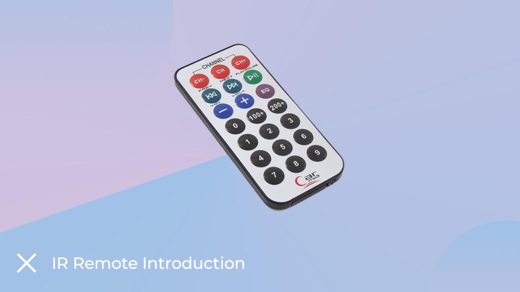
Note – You must remove the plastic under the coin cell before using the remote. If you don’t remove the plastic, the remote won’t work.
It was about the IR transmitter; Now we will talk about the second section of the unit and that is IR Receiver, it is nothing but a photoreceiver. When you press any button on the remote, that button connects to the timer IC and then the IC turns on the IR LED in a specific pattern.
That pattern is then received by the IR receiver where the IR receiver decodes the received signal and sends it to the control unit.
It was about the basics of IR remote. In the next section, we will understand the interfacing of IR module with Arduino.
IR Remote Interfacing With Arduino
In this section, we will understand how to interface IR receiver with Arduino. The IR module that you are getting with this module has three pins to connect to any microcontroller or any microprocessor. I have explained the function of those pins below.
GND – Here we have to connect the GND pin of the Arduino to this pin.
VCC – Connect the Arduino’s 5V pin to this pin.
Signal – You will find the module’s output on that pin. You can connect this pin of the module to any GPIO pin of the Arduino.
In my case, I have connected this pin to the 5-digit pin of Arduino.
You can also refer to the following image to understand the interfacing properly.
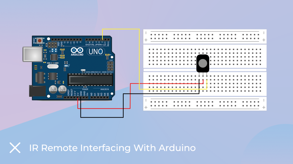
IR remote interfacing diagram
Arduino Code Introduction
In this part of this blog, we will understand the code that you can use to understand the functionality of IR remote.
So, let’s get back to the discussion of the Arduino code for the IR remote. We will find an IR remote library on the internet.
After downloading the library, add that Arduino library to the Arduino IDE. If you do not know how to add a library to the Arduino IDE, you can refer to this link.
As you know how to add a library, you can add the following library to the Arduino IDE.
Ok, now you can use the following code to start working with the IR module.
The following code will turn on the IR module and print whatever the IR module receives on the serial monitor.
Once you start receiving the output of the IR sensor, you can use that output and assign that output to a specific function of code, when the particular output is received from the IR receiver, Arduino will instantiate the specific function in our code.
This is it about the IR receiver, if you have any doubts then please let us know in the comment section.
Arduino Code For IR Remote
#include <IRremote.h>
int RECV_PIN = 11; // the pin where you connect the output pin of sensor

IRrecv irrecv(RECV_PIN);
decode_results results;

void setup() {
irrecv.enableIRIn(); // Start the receiver
}


void loop() {
if (irrecv.decode(&results)) {
unsigned int value = results.value;
Serial.print("IR Code is = ");
}
irrecv.resume(); // Receive the next value
}

}
So, this is how we learned about IR sensors. In the next part of this blog, we will learn about the seven-segment display.
Seven Segment Display Module
A 7-segment display is nothing but a pack of seven LEDs connected together where each LED is known as a segment. All of them can be controlled individually.
7-Segment displays are available in various colours (Red, Blue, and Green) and sizes (0.56 to 6.5 inches). Sometimes two to four 7-segment displays are packed together to form a big display (refer to the following image).
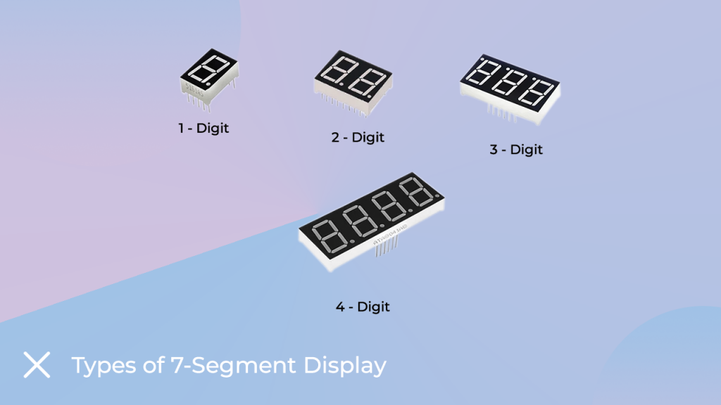
Types Of Seven Segment Display
We have written a blog on seven-segment displays. You can check This link to understand the working of the seven-segment display.
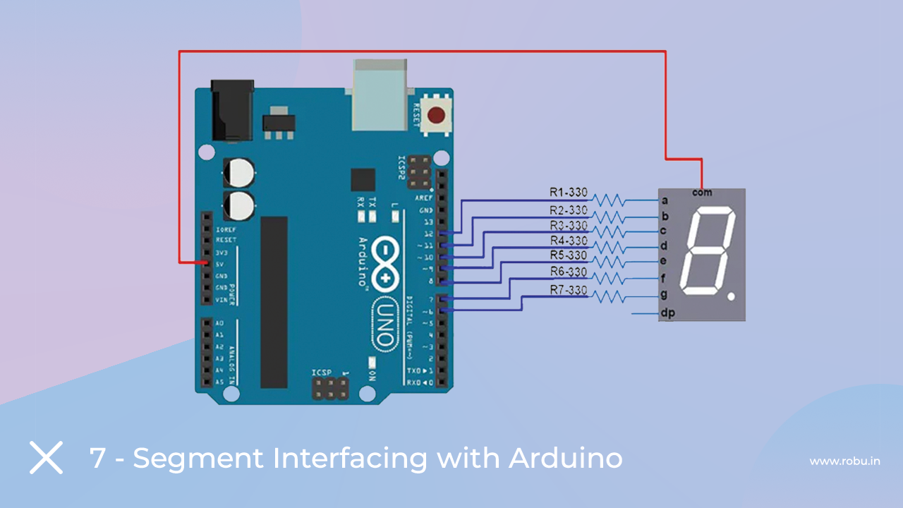
Seven Segment Display Interfacing With Arduino
Each LED in 7-segment display is connected separately to GPIO pins on Arduino board.
For interfacing purpose let we consider a common anode (CA) 7-segment display.
As the anode is the common terminal here so let us connect it to the 5V supply on Arduino. The remaining pins will be connected to the GPIO pins on Arduino.
We will be using separate wiring (refer to the connection diagram) for each LED segment and turn on the display in an ornate fashion.
Arduino Code For Seven Segment Display
The code for the seven-segment display is very easy and you don’t need to install any library to work with the seven-segment display.
You can use the following code to work with the seven-segment display.
One more thing to understand the logic of the Arduino code; you can refer to the following truth table.
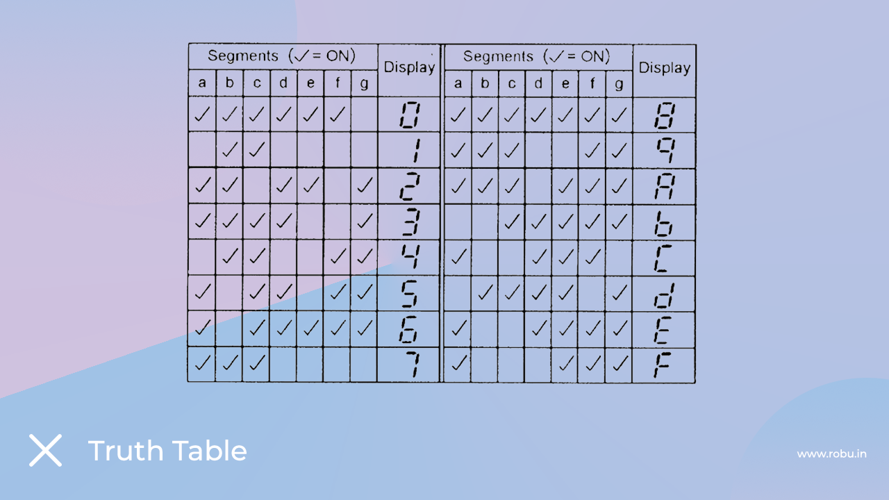
If you have any doubts, you can comment below.
void setup()
{
  // define pin modes

 pinMode(2,OUTPUT);
 pinMode(3,OUTPUT);
 pinMode(4,OUTPUT);
 pinMode(5,OUTPUT);
 pinMode(6,OUTPUT);
 pinMode(7,OUTPUT);
 pinMode(8,OUTPUT);

}

void loop()
{
  // loop to turn leds od seven seg ON

  for(int i=2;i<9;i++)
  {
    digitalWrite(i,HIGH);
    delay(600);
  }

  // loop to turn leds od seven seg OFF
  for(int i=2;i<9;i++)
  {
    digitalWrite(i,LOW);
    delay(600);
  }


  delay(1000);

}
Potentiometer
You must have seen the variable knob on the audio system. We use that knob to adjust the sound level.
In electronic terms, that knob is called a potentiometer and is nothing but a variable resistor. The output of the potentiometer varies according to the change in resistance.
It has three pins. I have mentioned the functionality of those pins below.
GND – Here you can connect the GND pin of the power source
Vcc – The positive pin of the power supply will be connected to this pin.
Signal – On this pin you will find the output of the potentiometer.
It was about the introduction of the potentiometer. In the next part of this blog, we will learn how to interface a potentiometer with Arduino.
Interfacing Potentiometer With Arduino
Interfacing the potentiometer with the Arduino is so easy. Here you have to connect the GND pin of the Arduino to the GND pin of the potentiometer and the VCC pin of the Arduino to the VCC pin of the potentiometer.
Talking about the output pin of the potentiometer, you can connect to any GPIO pin of the Arduino.
Please refer to the following image to understand the connection diagram.
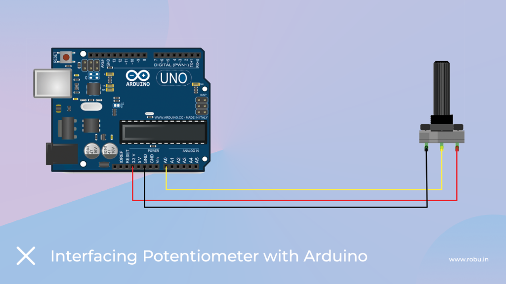
Interfacing Potentiometer with the Arduino
Arduino Code For Potentiometer
Since the interfacing diagram of the potentiometer is easy, the Arduino code for it is also easy. You can use below code to work with potentiometer.
You will see the output of the code on the serial monitor.
/*
by: di2tnugraha
https://www.youtube.com/kenziechannel
 */
int led = 11;
int pinPot = 0;
int potVal = 0;

void setup() {
   Serial.begin(9600);
   pinMode(led, OUTPUT);

}

void loop() {
    potVal = analogRead(pinPot);
    potVal = map(potVal, 0, 1023, 0, 255);
    analogWrite(led, potVal);
    Serial.println(potVal);
    delay(200);
}
So, in this way, you learned how to interface the potentiometer to Arduino. In the next part of this blog, you will learn about the flame sensor.
IR Flame Sensor
There are different flame sensors available in the market. What you are getting with this kit is an IR flame sensor.
IR flame sensor is used in fire system. They detect a fire and send a signal to the controlling unit, then the controlling unit takes the necessary action to avoid fire damage. But do you know
How does IR flame sensor detect fire?
The answer to this question is, IR sensors are designed to capture visible gases in the infrared spectral band.
When an explosion occurs, the light produced by the flames is reflected in the infrared spectral band and generates a flame sensor signal based on the received frequency of the light.
It was about the introduction of the flame sensor; Also in the next section of the blog, we will learn about interfacing the flame sensor with Arduino.
Interfacing Flame Sensor With Arduino
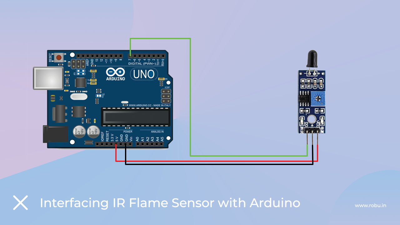
As we know that IR flame sensor has three pins, it is so easy to interface the IR flame sensor with Arduino.
You just need to connect the signal pin of the flame sensor to the analog pin of the Arduino and the second power pin of the sensor to the power pin of the Arduino.
Please refer to the image below to understand the wiring diagram.
Arduino Code For Flame Sensor
As you have connected the IR flame sensor to the Arduino, we will now move to the Arduino code section of the flame sensor.
The code is very simple and does not require any explanation. In this code, we have used a variable and the function of that variable is to collect the output of IR flame sensor.
Then we are printing that output to the serial monitor.
Please use the below code.
// lowest and highest sensor readings:
const int sensorMin = 0;     // sensor minimum
const int sensorMax = 1024;  // sensor maximum

void setup() {
  // initialize serial communication @ 9600 baud:
  Serial.begin(9600);
}
void loop() {
  // read the sensor on analog 9:
	int sensorReading = analogRead(7);
  // map the sensor range (four options):
  // ex: 'long int map(long int, long int, long int, long int, long int)'
	int range = map(sensorReading, sensorMin, sensorMax, 0, 3);

  // range value:
  switch (range) {
  case 0:    // A fire closer than 1.5 feet away.
    Serial.println("** Close Fire **");
    break;
  case 1:    // A fire between 1-3 feet away.
    Serial.println("** Distant Fire **");
    break;
  case 2:    // No fire detected.
    Serial.println("No Fire");
    break;
  }
  delay(1);  // delay between reads
}
Buzzer
Buzzers are used in many instruments. It is used as an indicator in many systems such as home appliances, alarm systems, electronic bells.
Talking about the working principle of the buzzer, the buzzer converts electrical energy into sound energy.
When voltage is applied to the buzzer, the piezo crystal expands and contracts inside the plastic casing. This causes the plate to vibrate near the crystal and the sound you hear is of that vibration.
Changing the frequency to the buzzer changes the speed of the vibration and, as a result, you hear a variety of sounds.
So, it was about the buzzer. There are two main types of buzzers. Active buzzer and passive buzzer. In the next section of this blog, we will now understand the difference between these two types.
Difference Between Active And Passive Buzzer
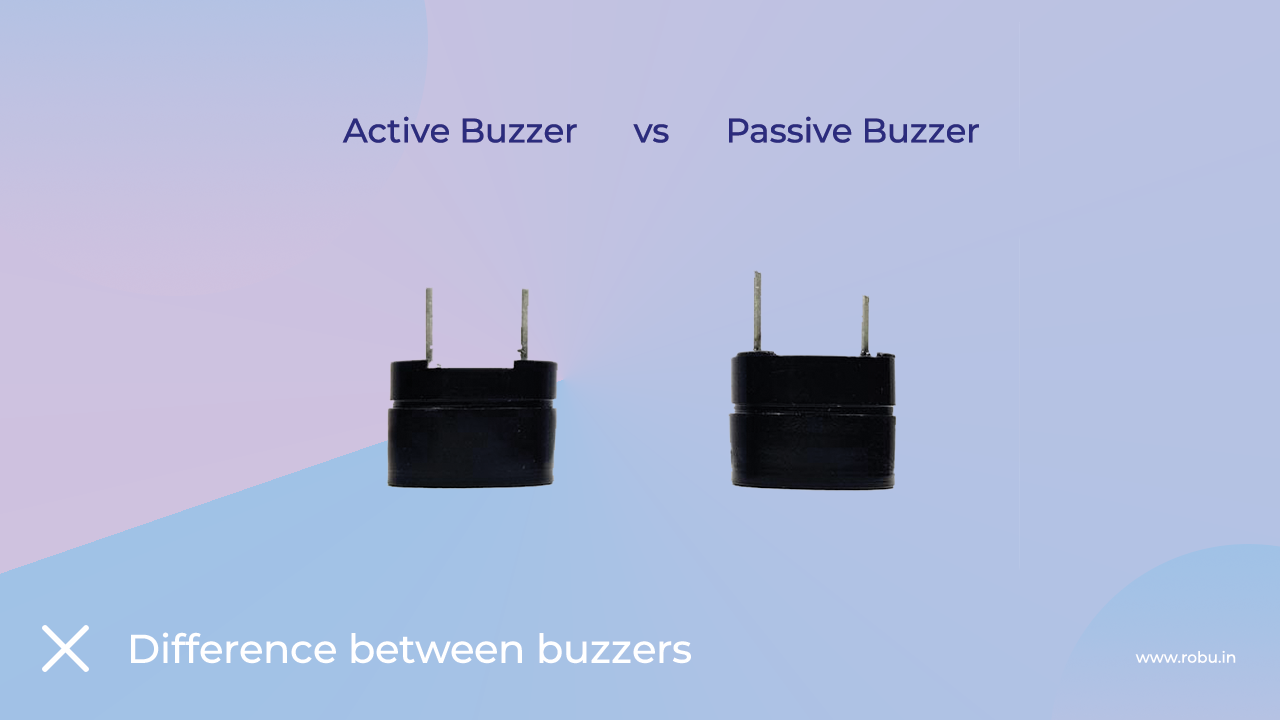
As I mentioned earlier, there are many types of buzzers. Active buzzer and passive buzzer.
Talking about the active buzzer, it has an inbuilt oscillating source. Active buzzer starts ringing as soon as you turn it on but in case of passive buzzer, they do not have an inbuilt oscillating source.
If you want a passive buzzer to produce a sound signal, you must give a different frequency to the buzzer.
Interfacing Buzzer with Arduino
No matter which buzzer you are using, it only has two pins. You can connect the VCC pin of the buzzer directly to the GPIO pin of the Arduino and the GND pin of the buzzer to the GND pin of the Arduino.
In my case, I have used an active buzzer. But you can use passive buzzer, maybe remember, if you want to make a different sound from passive buzzer here, you have to give a different frequency to the VCC pin of the buzzer.
Please check the interfacing diagram given below to understand the interfacing diagram.

As you have wired the buzzer. Now, we will move on to the Arduino code for the buzzer.
Arduino Code For Buzzer
The code for the buzzer is very simple. You just need to use the digital write function and apply high or low voltage to turn the buzzer on or off.
You can use the following code to turn on the buzzer.
const int buzzer = 8; //buzzer to arduino pin 9


void setup(){

  pinMode(buzzer, OUTPUT); // Set buzzer - pin 9 as an output

}

void loop(){

  tone(buzzer, 1000); // Send 1KHz sound signal...
  delay(1000);        // ...for 1 sec
  noTone(buzzer);     // Stop sound...
  delay(1000);        // ...for 1sec

}
Vibration Sensor
Vibration sensors are used in many devices such as mechanical machines. It is used to measure the frequency of vibrations generated by machines and those measured frequencies are then converted into voltage signals.
The vibration sensor we get with this kit has an onboard gain amplifier. That amplifier is used to adjust the gain of the module. If the signals generated by the vibration sensor are not accurate you can adjust the trimmer next to the gain amplifier.
There is a lot of information about vibration sensor, now we will talk about interfacing vibration sensor with Arduino.
Interfacing Vibration Sensor With Arduino
Interfacing the vibration sensor with Arduino is super easy. It has three pins, two for powering the module and one for output.
We need to connect the power pin of the vibration sensor to the Arduino and the signal pin to any GPIO pin of the Arduino.
You can refer to the following image to understand the wiring diagram.
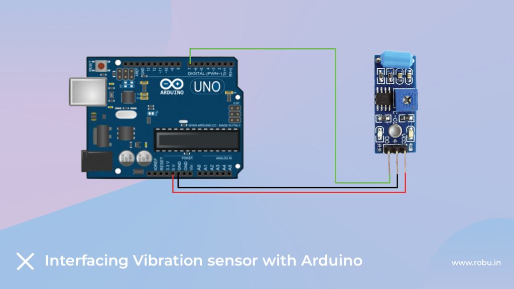
Interfacing Vibration Sensor With the Arduino
Arduino Code For Vibration Sensor
I have shared the code for the vibration sensor below. In this code, we are using analog read function and a global variable to read the output of the sensor. And the serial print function is used to print the output of the sensor.
int vib_pin=7;
int led_pin=13;
void setup() {
  pinMode(vib_pin,INPUT);
  pinMode(led_pin,OUTPUT);
}

void loop() {
  int val;
  val=digitalRead(vib_pin);
  if(val==1)
  {
    digitalWrite(led_pin,HIGH);
    delay(1000);
    digitalWrite(led_pin,LOW);
    delay(1000);
   }
   else
   digitalWrite(led_pin,LOW);
}
After uploading the code to the Arduino board, you can open the Serial Monitor and see the output there.
74HC595N 8 Bit Shift Register
Have you ever felt that your Arduino has fewer pins than the requirement? When I work with big projects I face these types of issues more often.
In those cases, we get only two options, either we use another Arduino and write part of the code for no reason or use a shift register.
Shift register not only saves our time but it also saves the bad connection that we make while working on a big project.
In this kit, we are using a 74HC595N shift register which has three input pins and eight output pins.
Now, we will understand the interfacing of 74HC595N with Arduino.
Interfacing 74HC595N With Arduino
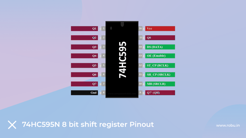
74HC595N 8 Bit Shift Register IC
So, before we talk about interfacing a multiplexer with Arduino, we will understand the pinout of the IC.
This IC has 16 pins, out of which we will be using only 11 pins. Pin numbers are 1,2,3,4,5,6,7, and 15 are output pins and 14, 12 and 11 are data pins.
Now we have to enable the IC to work with this IC. And to enable IC we need to connect GND pin of Arduino to IC’s 8, 10 and 13.
The reason for connecting the GND pin to those pins is because those pins are active low pins so to enable those pins we have to provide low-level signals to those pins.
This is about the introduction part of IC. In the next part of this blog, we will understand how to program the Arduino.
Arduino Code For 74HC595N
I have designed the following Arduino code for 74C595N. This code is generating the output on the output pin of the 74C595N.
int latchPin = 5;	// Latch pin of 74HC595 is connected to Digital pin 5
int clockPin = 6;	// Clock pin of 74HC595 is connected to Digital pin 6
int dataPin = 4;	// Data pin of 74HC595 is connected to Digital pin 4

byte leds = 0;		// Variable to hold the pattern of which LEDs are currently turned on or off

/*
 * setup() - this function runs once when you turn your Arduino on
 * We initialize the serial connection with the computer
 */
void setup()
{
  // Set all the pins of 74HC595 as OUTPUT
  pinMode(latchPin, OUTPUT);
  pinMode(dataPin, OUTPUT);
  pinMode(clockPin, OUTPUT);
}

/*
 * loop() - this function runs over and over again
 */
void loop()
{
  leds = 0;	// Initially turns all the LEDs off, by giving the variable 'leds' the value 0
  updateShiftRegister();
  delay(500);
  for (int i = 0; i < 8; i++)	// Turn all the LEDs ON one by one.
  {
    bitSet(leds, i);		// Set the bit that controls that LED in the variable 'leds'
    updateShiftRegister();
    delay(500);
  }
}

/*
 * updateShiftRegister() - This function sets the latchPin to low, then calls the Arduino function 'shiftOut' to shift out contents of variable 'leds' in the shift register before putting the 'latchPin' high again.
 */
void updateShiftRegister()
{
   digitalWrite(latchPin, LOW);
   shiftOut(dataPin, clockPin, LSBFIRST, leds);
   digitalWrite(latchPin, HIGH);
}
So, it was about the components that we are getting in this kit. In the next section, we’ll be working on some projects using the components of this kit.
Projects Using Orange Beginner Kit
In this section of this blog, we will learn about different types of projects that we can design with the help of this kit.
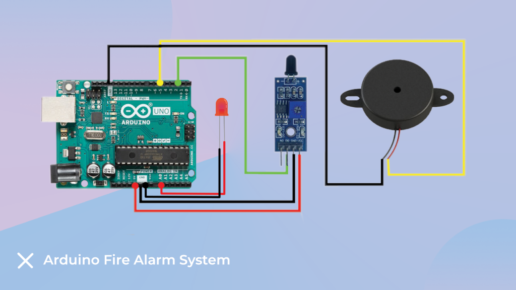
Detecting Fire Using Arduino
You must have seen fire alarm systems in many places. Such systems are designed to avoid casualties in an explosion.
To complete this project, we are going to use the following components.
List of The Components
- Arduino
- Jumper Cable
- Flame Sensor
- Active Buzzer
- Bread baord
Interfacing Diagram For Fire Alarm System
In this project, we are using flame sensor to detect fire and for alarming purposes, we are using an active buzzer.
First, we will connect the flame sensor’s signal pin to pin number seven and the flame sensor’s power pin to the Arduino’s power pin.
Now, as I told you earlier, we are using the active buzzer as an indicator. So, we need to connect the VCC pin of the flame sensor to the 5v pin of the Arduino.
Please check the following interfacing diagram to understand the connection.
Arduino Code For Fire Alarm System
The following code is designed for the fire alarm system. In this code, we are reading the output of the flame sensor and comparing the output of the flame sensor with the threshold value.
When the output value of the flame is crossing the set value we are turning on the buzzer.
So this was about the Fire alarm system. You can use the following code now.
According to me you may not have any issue. but if you face any issue, please mention your issue in the comment section. However, if you found any discrepancy, kindly comment below.
    #define Fire_sensor 2
    #define Buzzer 5
    #define Light A0
    #define ldelay 500
    #define bdelay 500
    void setup() {
        Serial.begin(9600);
        pinMode(Fire_sensor, INPUT);
        pinMode(Buzzer, OUTPUT);
        pinMode(Light, OUTPUT);
    }
    void loop() {
        if (int a = digitalRead(Fire_sensor) == LOW) {
            alert();
        } else {
            digitalWrite(Buzzer, LOW);
            digitalWrite(Light, LOW);
        }
    }
    void alert() {
        digitalWrite(Light, HIGH);
        digitalWrite(Buzzer, HIGH);
        delay(ldelay);
        digitalWrite(Light, LOW);
        digitalWrite(Buzzer, LOW);
        delay(ldelay);
        digitalWrite(Light, HIGH);
        digitalWrite(Buzzer, HIGH);
        delay(ldelay);
        digitalWrite(Light, LOW);
        digitalWrite(Buzzer, LOW);
        delay(ldelay);
        digitalWrite(Light, HIGH);
        digitalWrite(Buzzer, HIGH);
        delay(ldelay);
        digitalWrite(Light, LOW);
        digitalWrite(Buzzer, LOW);
        delay(ldelay);
    }
Vibration Detection Using Arduino
As we discussed in the section of the vibration sensor, vibration sensor are used to detect frequency of the object on which they are mounted.
We have already talked about the basic things so you check the required information in the above section of the blog.
List of The Components
- Bread Board
- Arduino
- Vibration Sensor
- Connecting wires
- Buzzer
Interfacing Diagram For Vibration Sensor –
The connection diagram is similar to the diagram shown in the above sections.
We have installed vibration sensor on breadboard and its signal pin is connected to GPIO pin of Arduino.
You can refer to the following image to understand the connection diagram.

Interfacing Vibration Sensor With The Arduino
Arduino Code For Vibration Sensor
We are using the same logic the one that we used in our previous section. In the code below we have used a variable to store the output of the sensor.
And once the output of the senor crosses the certain limit the code will turn on the buzzer.
You can use the following code and see the results by vibrating the sensor.
If you have any doubts about this section please let me know in the comment section.
int vib_pin=7;
int led_pin=13;
void setup()
{

pinMode(vib_pin,INPUT);
pinMode(led_pin,OUTPUT);

}
void loop() {
int val;
val=digitalRead(vib_pin);
if(val==1)
{
digitalWrite(led_pin,HIGH);
delay(1000);
digitalWrite(led_pin,LOW);
delay(1000);
}
else
digitalWrite(led_pin,LOW);
}
Conclusion –
So, in this way we have learned about the components that we are getting with the orange Arduino beginner kit.
We also have learned about the projects that we can design using the components of this kit.
I have covered everything that is needed to learn this kit in a better way. However, if you found any discrepancy, kindly comment below.