Hello, we have already gone through the introduction of the STM32 discovery board. Today we are going to interface the Infrared Sensor with STM Board. If you are a beginner in using STM programming, you will understand the interrupt handling and use of GPIO pins. Let’s get started!
Components Required:
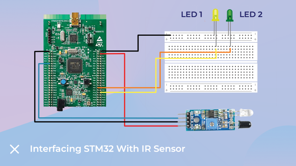
Interfacing Diagram:
The following picture depicts the interfacing between the IR module and STM32 DISC Board. PA1 pin introduces interrupt as IR sensor detects an obstacle. The LED connected at PD1 indicates the interrupt status.

Pinout:
- LED1- PD0 (Pin 0 of Port D)
- LED2- PD1 (Pin 1 of Port D)
- IR (5V)- 5V of STM Board
- IR (Gnd)- GND of STM
- IR (Dout)- PA1 (Pin 1 of Port A)
Software:
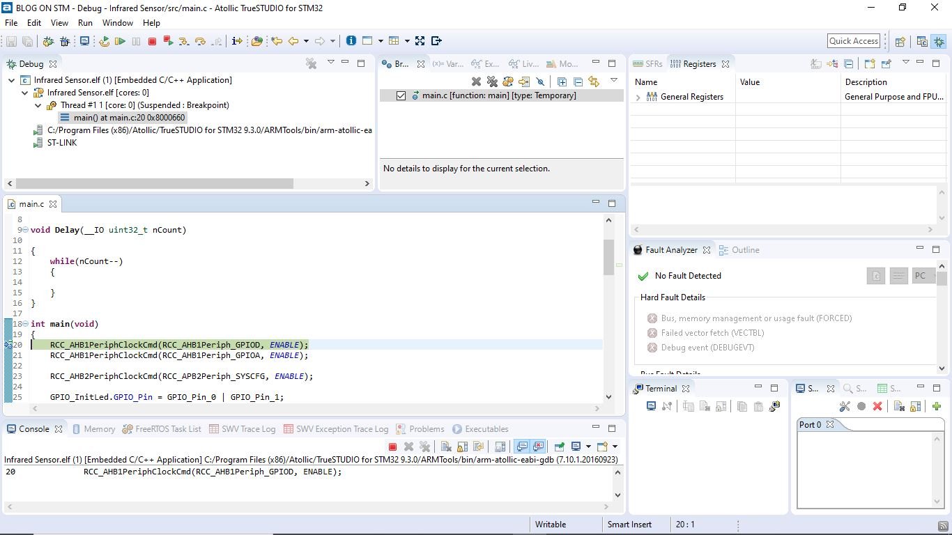
Let’s move towards code writing and deployment. I have used Atollic Truestudio for the programming of the board. The initial steps are software installing and selecting the board. After that, go to Files–>New Project–>C project and the perspective of the new project will open, as you can see in the following image.
- Step 1: Create New Project.
- Step 2: Write Code.
- Step 3: Save.
- Step 4: Build Project.
- Step 5: Debug.

In the Debugger perceptive, press the resume button to run the code on STM32 Board.
Code:
STM32F GPIO pins are classified as Port A, Port B, Port C etc. All these ports are inactive by default. However, if we have to use them, we must enable the clock at a particular GPIO.
RCC_AHB1PeriphClockCmd(RCC_AHB1Periph_GPIOD, ENABLE); //Enable GPIOD clock
RCC_AHB1PeriphClockCmd(RCC_AHB1Periph_GPIOA, ENABLE); //Enable  GPIOA clock
RCC_AHB2PeriphClockCmd(RCC_APB2Periph_SYSCFG, ENABLE); // Enable SYSCFG clock
GPIO_InitLed.GPIO_Pin = GPIO_Pin_0 | GPIO_Pin_1; // GPIOs as output push-pull to drive external GPIO_InitLed.GPIO_Mode = GPIO_Mode_OUT; // Define as output port.
GPIO_InitLed.GPIO_Speed = GPIO_Speed_50MHz;
The speed at these pins cannot be exact 50MHz. But, by using this line, we are trying to get the maximum possible speed at it.
GPIO_Init(GPIOD, &GPIO_InitLed);// Apply all above configurations.Normally, STM32 boards have a total of 23 interrupt sources which can be classified into two sections. One section is for GPIO pins from P0 to P15 on each port, and the other is for RTC, Ethernet and USB interrupts. As PA0 and PB0 are connected to Line 0, we can not use them simultaneously. However, PA2 and PA6 can be used at a time as they are connected to different lines.
SYSCFG_EXTILineConfig(EXTI_PortSourceGPIOA, EXTI_PinSource1);//Connect EXTI at Line1 to PA1 pin
/*Configuration of EXTI at Line1.*/

EXTI_InitSensor.EXTI_Line = EXTI_Line1;
EXTI_InitSensor.EXTI_Mode = EXTI_Mode_Interrupt;
EXTI_InitSensor.EXTI_Trigger = EXTI_Trigger_Rising;
EXTI_InitSensor.EXTI_LineCmd = ENABLE;
EXTI_Init(&EXTI_InitSensor);
NVIC_InitSensor.NVIC_IRQChannel = EXTI1_IRQn;// Selection of interrupt
The below lines sets the priority level of interrupt. i.e., the highest priority interrupt has a lower number from 0x00 to 0x0F.
NVIC_InitSensor.NVIC_IRQChannelPreemptionPriority = 0;
NVIC_InitSensor.NVIC_IRQChannelSubPriority = 0;
NVIC_InitSensor.NVIC_IRQChannelCmd = ENABLE;// enable interrupt.
void EXTI1_IRQHandler(void) // interrupt Handler for pin1 connected to line 1
{
	if(EXTI_GetITStatus(EXTI_Line1) != RESET)
	{
		GPIO_WriteBit(GPIOD, GPIO_Pin_1, Bit_SET);
		Delay(33600000);
		GPIO_WriteBit(GPIOD, GPIO_Pin_1, Bit_RESET);
          }
} // Interrupt handler
EXTI_ClearITPendingBit(EXTI_Line1);// Clear the EXTI line pending bit.The complete program is as follows.
#include "stm32f4xx.h"
#include "stm32f4_discovery.h"

GPIO_InitTypeDef GPIO_InitLed;
EXTI_InitTypeDef EXTI_InitSensor;
NVIC_InitTypeDef NVIC_InitSensor;

void Delay(__IO uint32_t nCount)

{
	while(nCount--)
	{

	}
}

int main(void)
{
	RCC_AHB1PeriphClockCmd(RCC_AHB1Periph_GPIOD, ENABLE);
	RCC_AHB1PeriphClockCmd(RCC_AHB1Periph_GPIOA, ENABLE);

    RCC_AHB2PeriphClockCmd(RCC_APB2Periph_SYSCFG, ENABLE);

	GPIO_InitLed.GPIO_Pin = GPIO_Pin_0 | GPIO_Pin_1;
	GPIO_InitLed.GPIO_Mode = GPIO_Mode_OUT;
	GPIO_InitLed.GPIO_OType = GPIO_OType_PP;
	GPIO_InitLed.GPIO_PuPd = GPIO_PuPd_NOPULL;
	GPIO_InitLed.GPIO_Speed = GPIO_Speed_50MHz;
        GPIO_Init(GPIOD, &GPIO_InitLed);

	GPIO_InitLed.GPIO_Pin = GPIO_Pin_1;
	GPIO_InitLed.GPIO_Mode = GPIO_Mode_IN;
	GPIO_InitLed.GPIO_Mode = GPIO_OType_PP;
	GPIO_InitLed.GPIO_PuPd = GPIO_PuPd_DOWN;
	GPIO_InitLed.GPIO_Speed = GPIO_Speed_50MHz;
	GPIO_Init(GPIOA, &GPIO_InitLed);


	SYSCFG_EXTILineConfig(EXTI_PortSourceGPIOA, EXTI_PinSource1);

	EXTI_InitSensor.EXTI_Line = EXTI_Line1;
	EXTI_InitSensor.EXTI_Mode = EXTI_Mode_Interrupt;
	EXTI_InitSensor.EXTI_Trigger = EXTI_Trigger_Rising;
	EXTI_InitSensor.EXTI_LineCmd = ENABLE;
	EXTI_Init(&EXTI_InitSensor);

	NVIC_PriorityGroupConfig(NVIC_PriorityGroup_1);

	NVIC_InitSensor.NVIC_IRQChannel = EXTI1_IRQn;
	NVIC_InitSensor.NVIC_IRQChannelPreemptionPriority = 0;
	NVIC_InitSensor.NVIC_IRQChannelSubPriority = 0;
	NVIC_InitSensor.NVIC_IRQChannelCmd = ENABLE;
	NVIC_Init(&NVIC_InitSensor);

	while (1)
  {
	GPIO_WriteBit(GPIOD, GPIO_Pin_0, Bit_SET);
	Delay(16800000);
	GPIO_WriteBit(GPIOD, GPIO_Pin_0, Bit_RESET);
	Delay(16800000);
  }
}
void EXTI1_IRQHandler(void)
{
	if(EXTI_GetITStatus(EXTI_Line1) != RESET)
	{
		GPIO_WriteBit(GPIOD, GPIO_Pin_1, Bit_SET);
		Delay(33600000);
		GPIO_WriteBit(GPIOD, GPIO_Pin_1, Bit_RESET);
		EXTI_ClearITPendingBit(EXTI_Line1);
     }

}
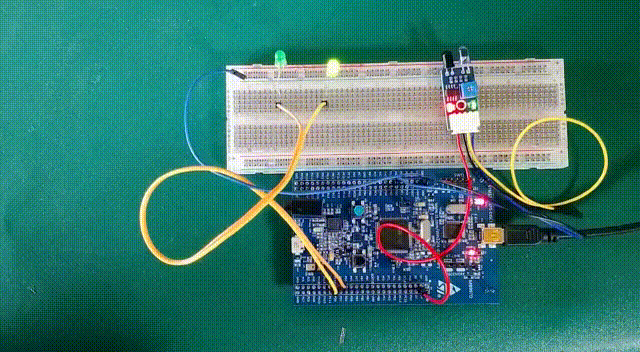
Output:
Final Words:
Hope you found this article informative. If you are interested to learn more about it, let us know your thoughts in the comment section.