In recent years, electronics and robotics have gradually integrated into our lives, so much that we are practically becoming inseparable from it.
Kids, hobbyists, people from non-technical background, and budding enthusiasts from all walks of life want to learn more about robotics and “how to build these robots?”. But here’s the thing-Learning new technology and building useful things are difficult tasks – Hence, Easy mech has come forward with an ingenious solution.
But first questions first.
What is EasyMech?
EasyMech is a brand of Robu.in which intends to make the life of users easy by providing easy-to-use mechanical products and Ready to assemble development kits.
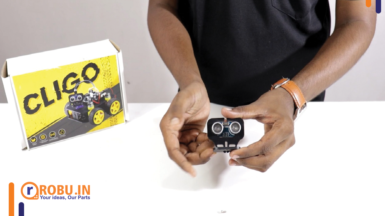
For most beginners, getting into robotics and embedded is a hard cookie to crack. With Cligo bot, you can do that very easily. In this tutorial, we will learn about assembling the Cligo bot as well as coding and running three different projects all with just one robot kit.
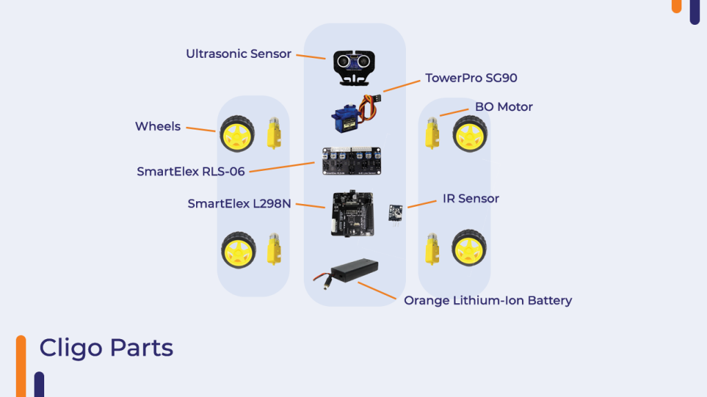
Before working with the bot itself, it is necessary to understand the components we get inside the Cligo bot package:
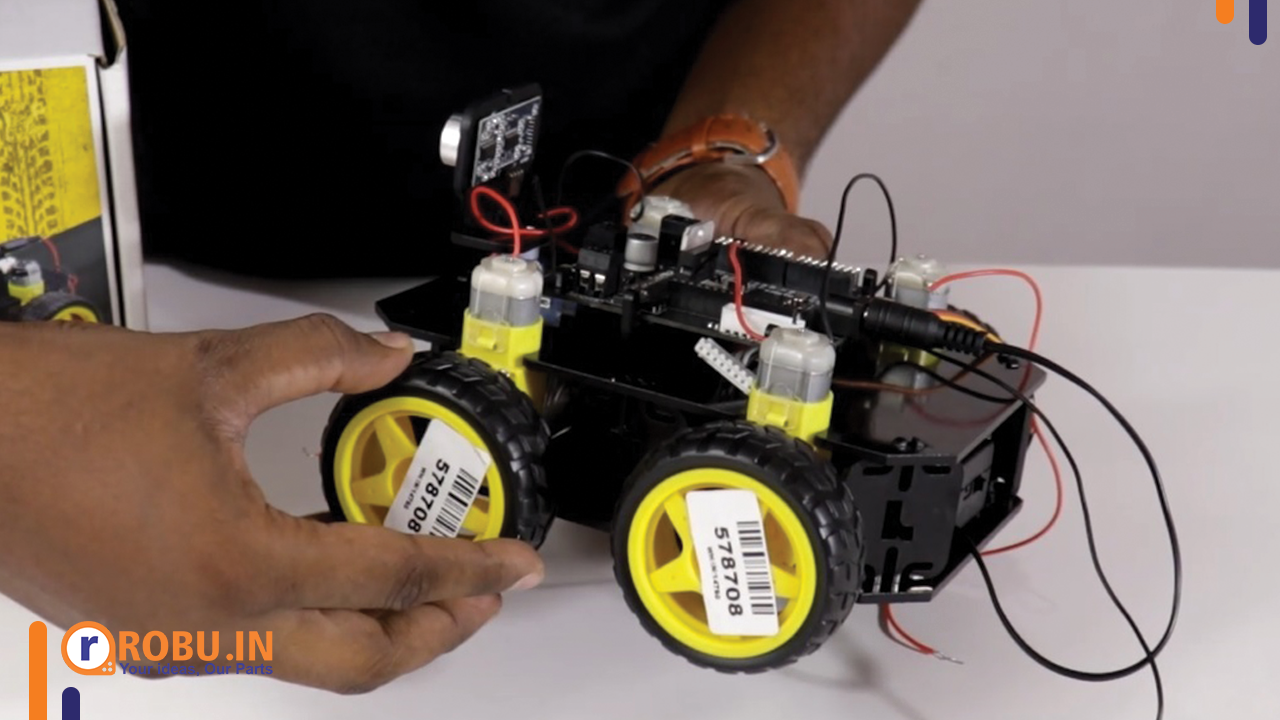
4 X 65mm Robot Wheel Grade B for BO Motors (Yellow)
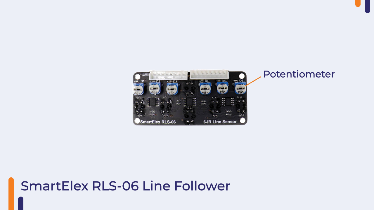
1 X SmartElex RLS-06 Analog & Digital Line Sensor Array
1 X Tower Pro SG90 1.2kgCm 180 Degree Rotation Servo Motor
1 X SmartElex L298N Motor Driver with On-board Arduino Uno.
2 X Orange ICR 18650 2500mAh Lithium-Ion Battery
1 X 18650 x 2 battery holder with cover and on/Off Switch with DC jack
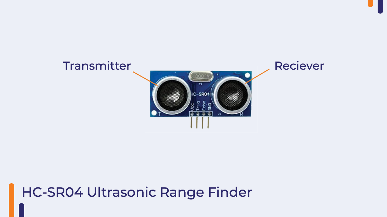
1 X HC-SR04-Ultrasonic Range Finder
1 X EasyMech Snap-fit ABS Bracket for HC-SR04 Ultrasonic Sensor
1 X Tomo V6-2 Dual USB 2 Slots Battery Intelligent Charger for AA / AAA / 18650 Batteries Black
1 X 20cm DuPont Wire Color Jumper Cable, 2.54mm 1P-1P Male to Female 40PCS
1 X 20cm DuPont Wire Color Jumper Cable, 2.54mm 1P-1P Female to Female 40PCS
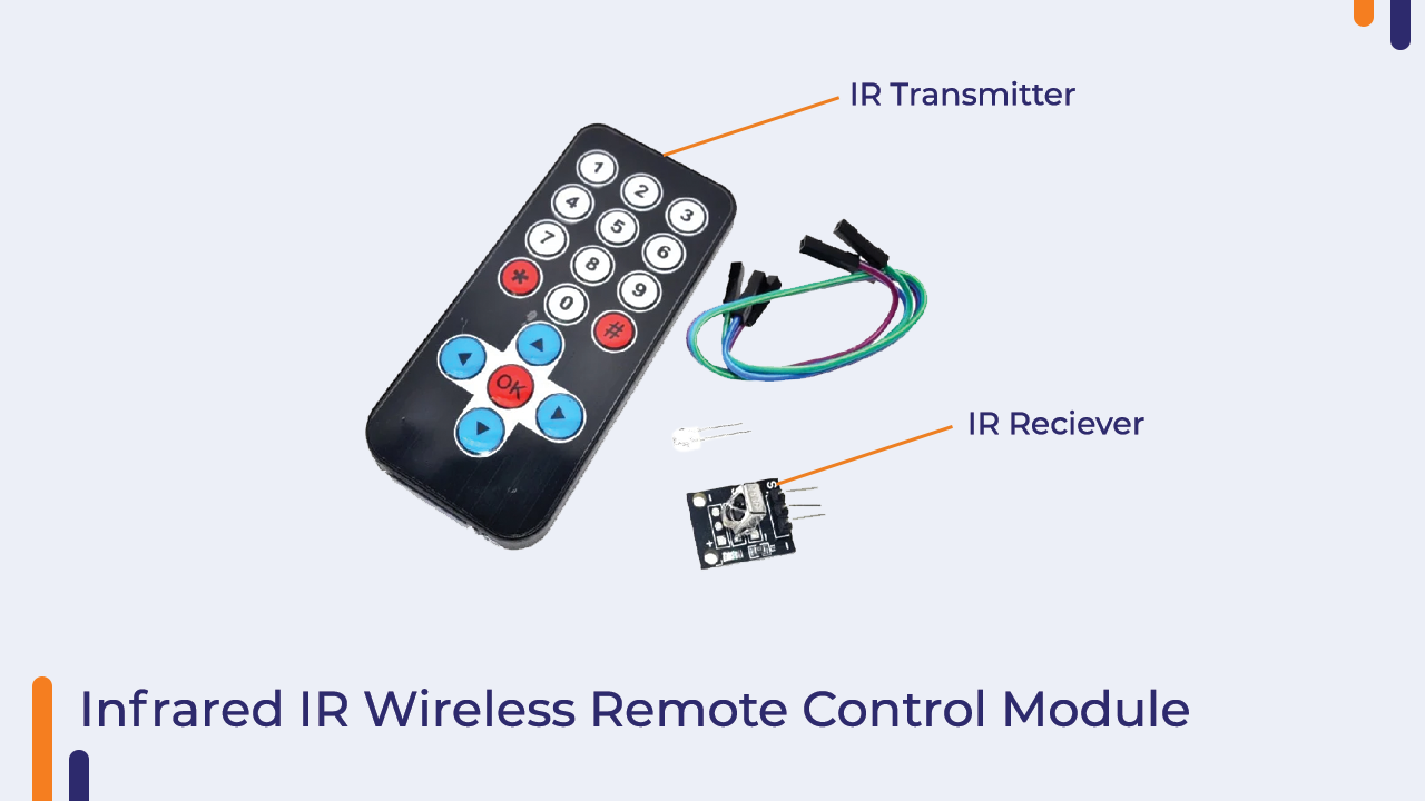
1 X Infrared IR Wireless Remote Control Module Kit for Arduino
1 X 2 in 1 Philips Screw Driver for DIY Robot Car
2 X 8mm Spiral Wrapping Band Black for Wires (cm)
1 X 3M Multipurpose Double Sided Sponge Glue Adhesive Dash pad 1 pcs
1 X Manual
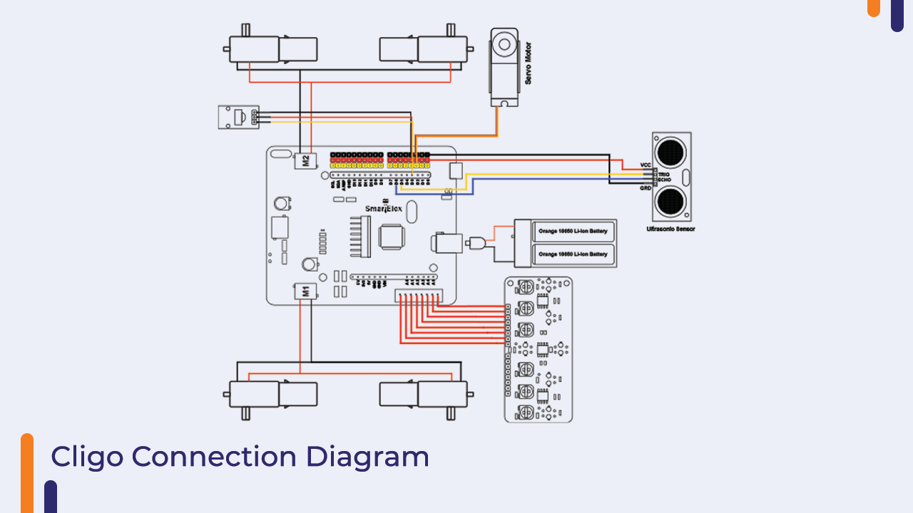
The image below describes the different parts of cligo bot and how they connect with each other seamlessly.

When you are working with circuits. It is important to understand what kind of circuit it is and how they work?. Let’s talk about the two most important circuit boards we have used while making the Cligo bot.
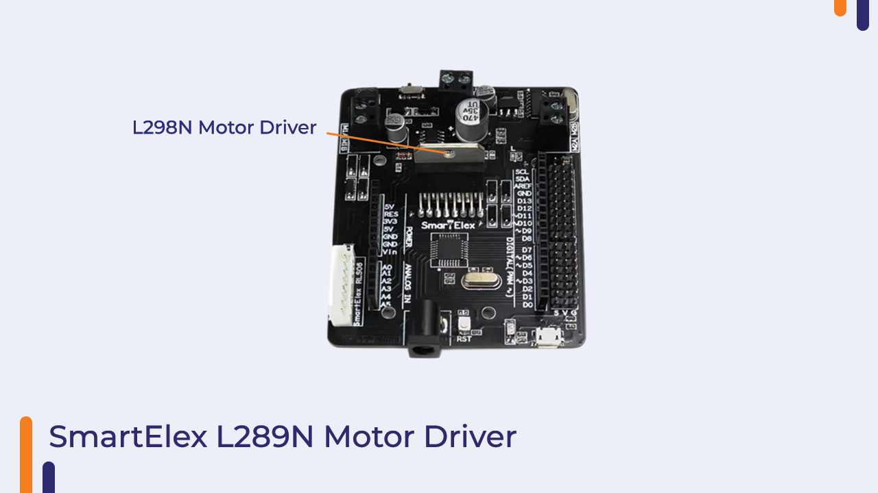
1)SmartElex L298N motor driver circuit.
For beginners, this circuit consists of an atmeg328p microcontroller which is essentially the brain of the whole bot connected to an l298n motor driver chip. The atmeg328p chip is where we upload our codes through the Arduino ide.
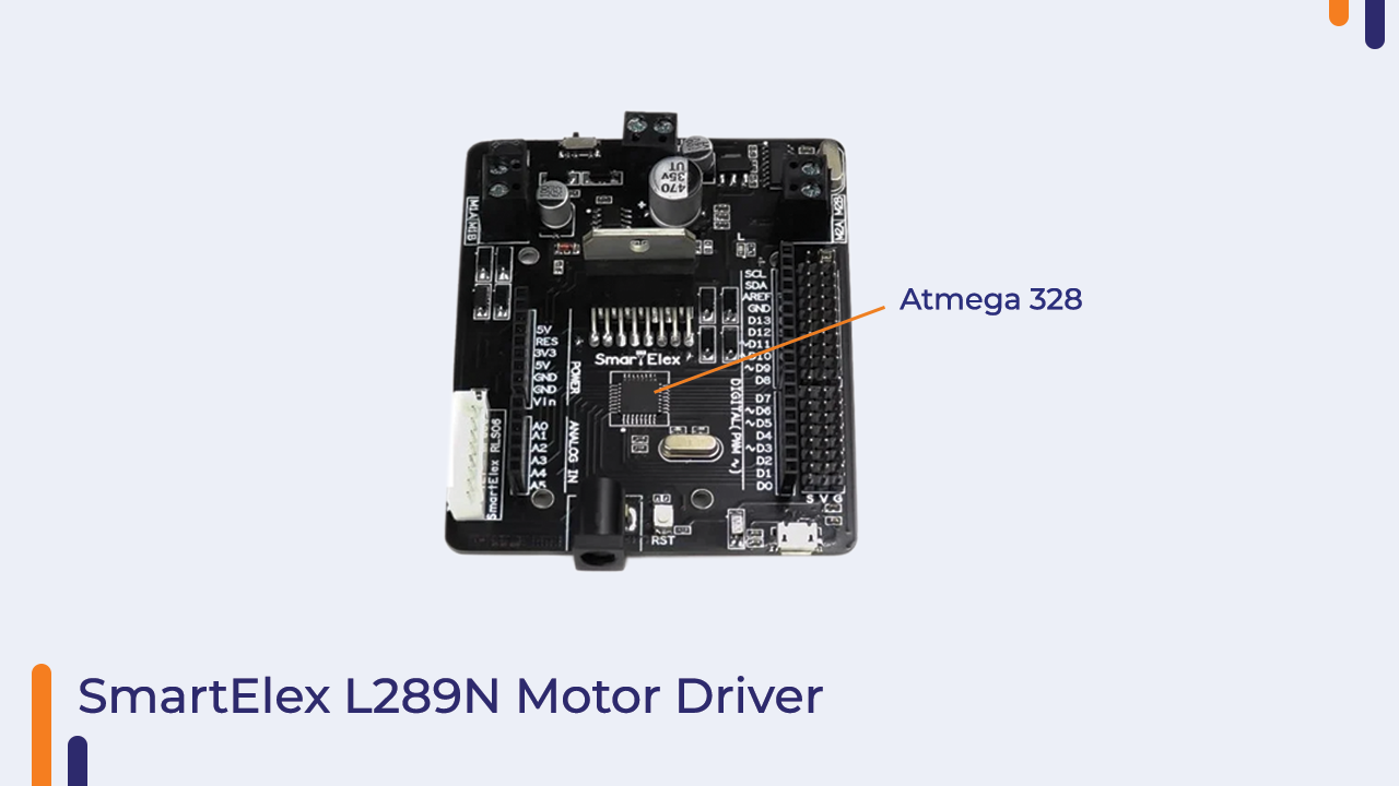
The l298n motor driver helps to change the direction and speed control of motors. The atmeg328p chip and l298n are connected in such a way where the former can send PWM signals to the latter for motor control.
2)SmartELex Line sensor circuit.
The line sensor circuit consists of 6 IR sensors. this will help us detect the difference between the black line and the ground.
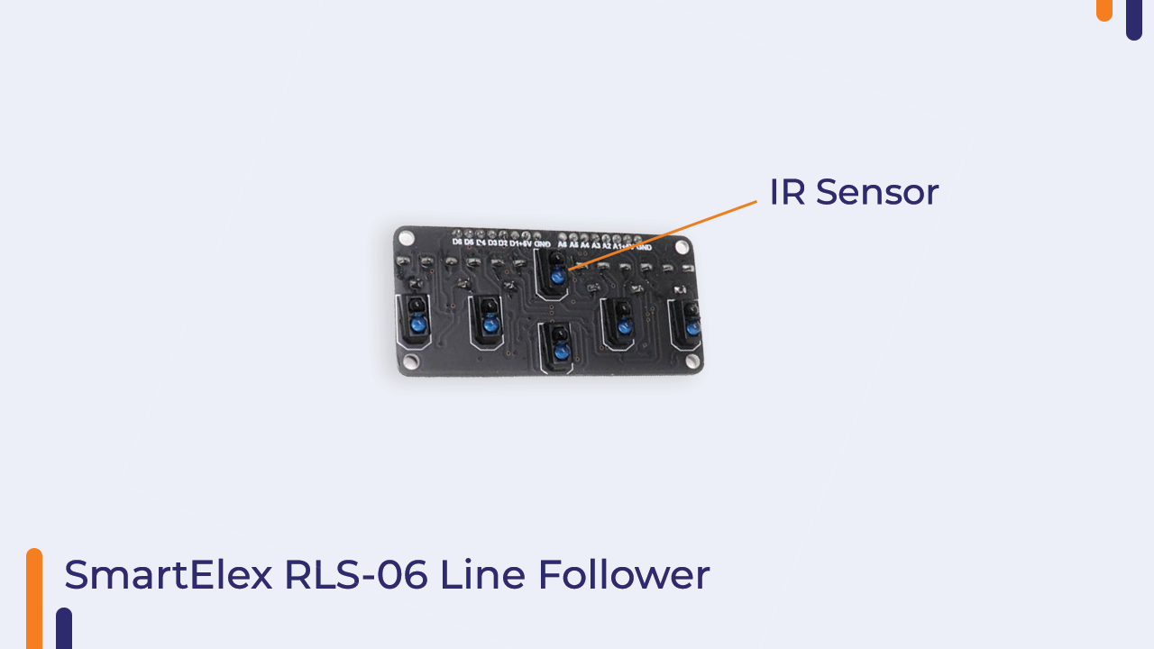
Note that sometimes these IR sensors require calibration so they are equipped with potentiometers above them, you can gently twist these potentiometers with the provided screwdriver to calibrate them.
We have the ultrasonic sensor which will help us detect the distance of any object from the sensor itself. the ultrasonic sensor sends ultrasonic waves through its transmitter junction and when these waves collide with an object and return to the receiver junction. we get the distance between any object at the front and the sensor by the time the waves took to travel to the object and back.
Similar to an Ultrasonic sensor, the IR remote works by transmission and reception of infrared signals. the take being that through the IR transmitter we can send information too and that is received at the IR receiver and then decoded further on through the atmeg328p chip.
Let’s Assemble The Bot Now.
The first step will be to take the base plate and then mount the SmartElex Line sensor array. Take a U bracket and push it inside the front rectangular hole with the line sensor enclosed in it. Connect the white cable in the first slot.

Next, mount the li-ion battery holder on the base plate with help of a 3M adhesive dash pad. You can put the 18650 batteries inside the holder but make sure you are putting the batteries properly into the holder i.e. Positive side is connected to the positive terminal of the holder and the negative side to the negative terminal. The battery holder has a switch. Make sure it is in “off” position during the assembly. Take the few side plates –squeeze and then push them gently in the spaces given on the base plate.

Assemble the servo mechanism as shown in the image below(Make sure to keep the ultrasonic pins on the top) . The next important step is to take the top plate and mount the servo motor (the blue motor) in the square slot in such a way where the moving part of the servo is at the front side.
After that has been taken care of, get the BO-motors (the yellow motors) and gently rotate them so they slip inside the space made for the motors. do this for all the motors.

Now take the base plate and attach it with the top plate with the motors. After doing this, make sure to pull the white cable connected to the Line sensor and the servo motor’s wire through the triangular hole. Take the U brackets and push them inside the rectangular holes. This will work as the stand for the SmartElex l298n circuit. Assemble the Ultrasonic sensor such that the pins are on the upside. The final step of assembly is to attach wheels to the motor.
Connect all the sensors and motors to the circuit as shown in the diagram given below.
In the next 3 steps, we will talk about how you can upload software into your board and run your cligo.
Step 1:
Download Arduino ide from here.
Download the codes and libraries for the bot from here and extract it in a folder.
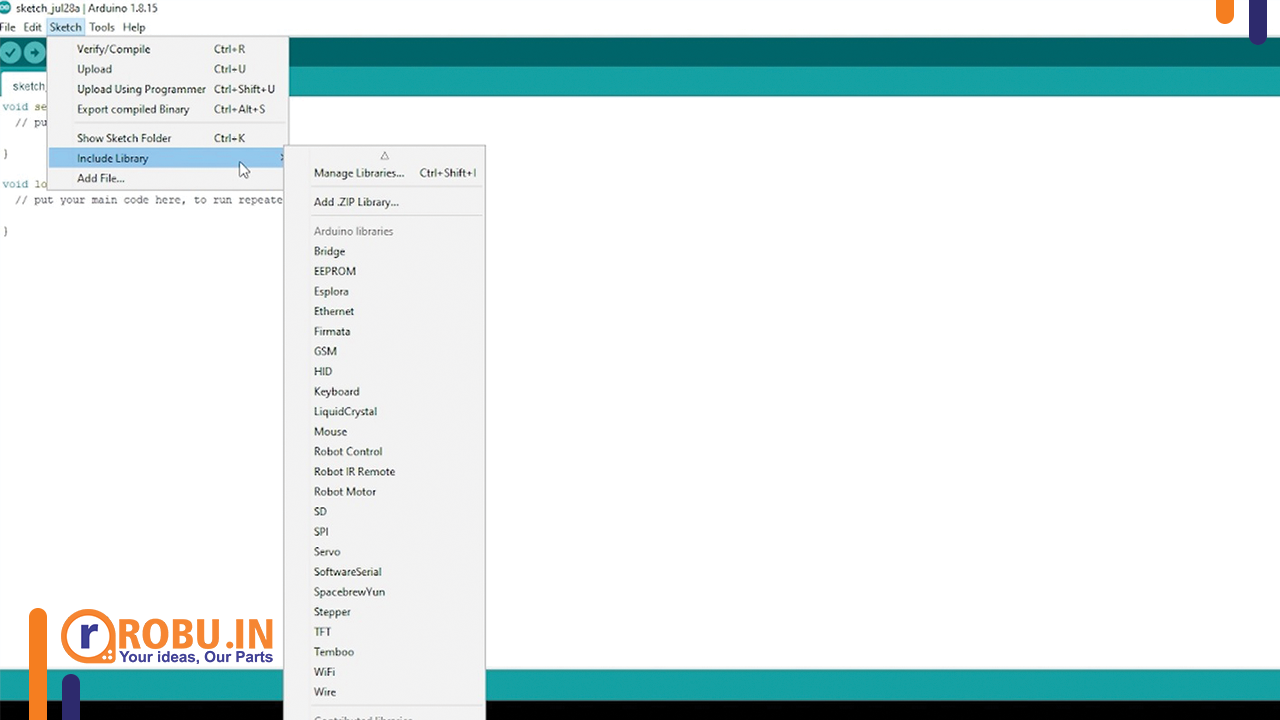
Install the Arduino IDE and make sure you include the two libraries (Servo-master and Arduino-IRremote-master)
Go to sketch> include>Add .zip library and include the two libraries one by one.
Step 2:
Download the CH340 USB driver for your system from here.
Extract the folder and install it in your system by clicking the “Install” button.
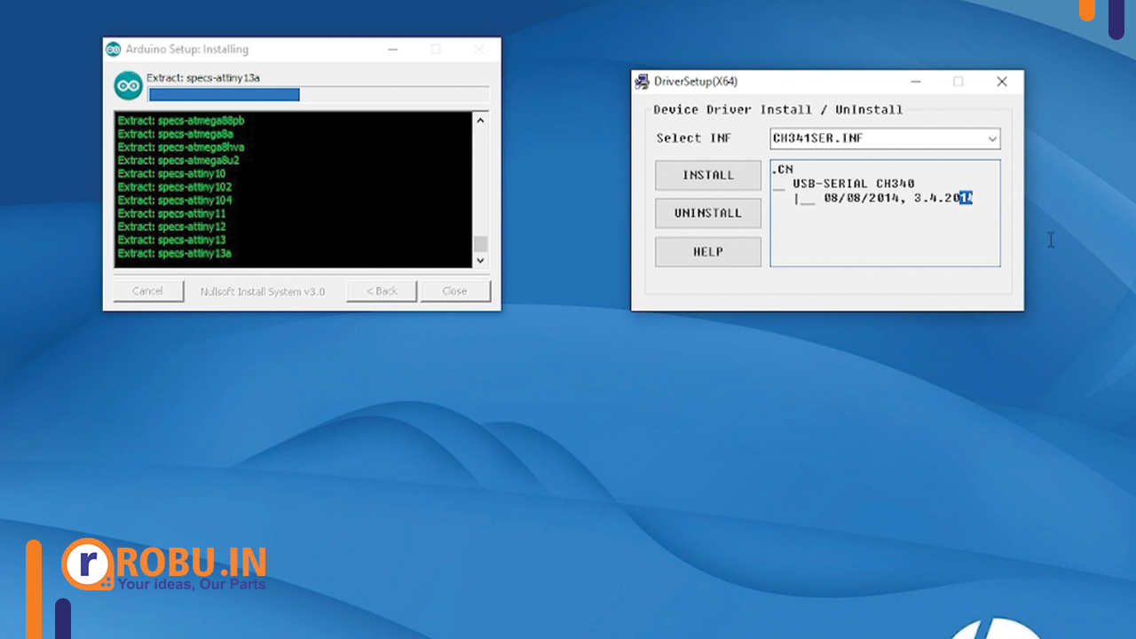
(Note: For Windows 8.1 and above, these drivers might already be installed and you may get an “error message”. In that case, you can skip the second step.)
Step3:
Connect USB to your PC and the bot. make sure the LEDs on the circuits are blinking. If not, switch on the sliding switch which is at the upper left corner of the SmartElexL298N circuit. If LED is blinking, it means that circuit is in the “ON” position.
Now go to Tools>Board and select Arduino Uno.
Next, select the port where you want to upload your program. You can check this by attaching and detaching USB from the bot. The port number which appears after you connect your USB will be your Board’s Port Number.
When this has been done go to File>Open
Navigate to the Codes and Libraries folder you downloaded in Step1 and Select whichever code you would like to run. Then hit on Upload button. That’s it.
The Cligo bot can be used in 3 different modes. The type of code you upload on the board will decide the mode the bot will work on.
- Line following mode: – Stick black tape to the ground. Connect the power connector to the board and push the holder switch to On position after uploading the code.
- Obstacle avoidance mode. Just upload the code and have fun looking at how the bot tries to avoid objects in its way.
- Remote controlled mode: -Upload the code and press forward, backward, right and left buttons on the remote to see the bot move.
If you are interested in getting this bot for yourself, you can click here.
You can refer to our video on YouTube too to get more ideas about this product.
Thanks for reading this blog.
Stay safe. Stay tuned at robu.in