
Since the raspberry pi pico came into the market, it has become the buzz of the town. It has become ideal for many to get their hands on this newest microcontroller. In this blog, you will learn how you can build a drone out of raspberry pi pico yourself.
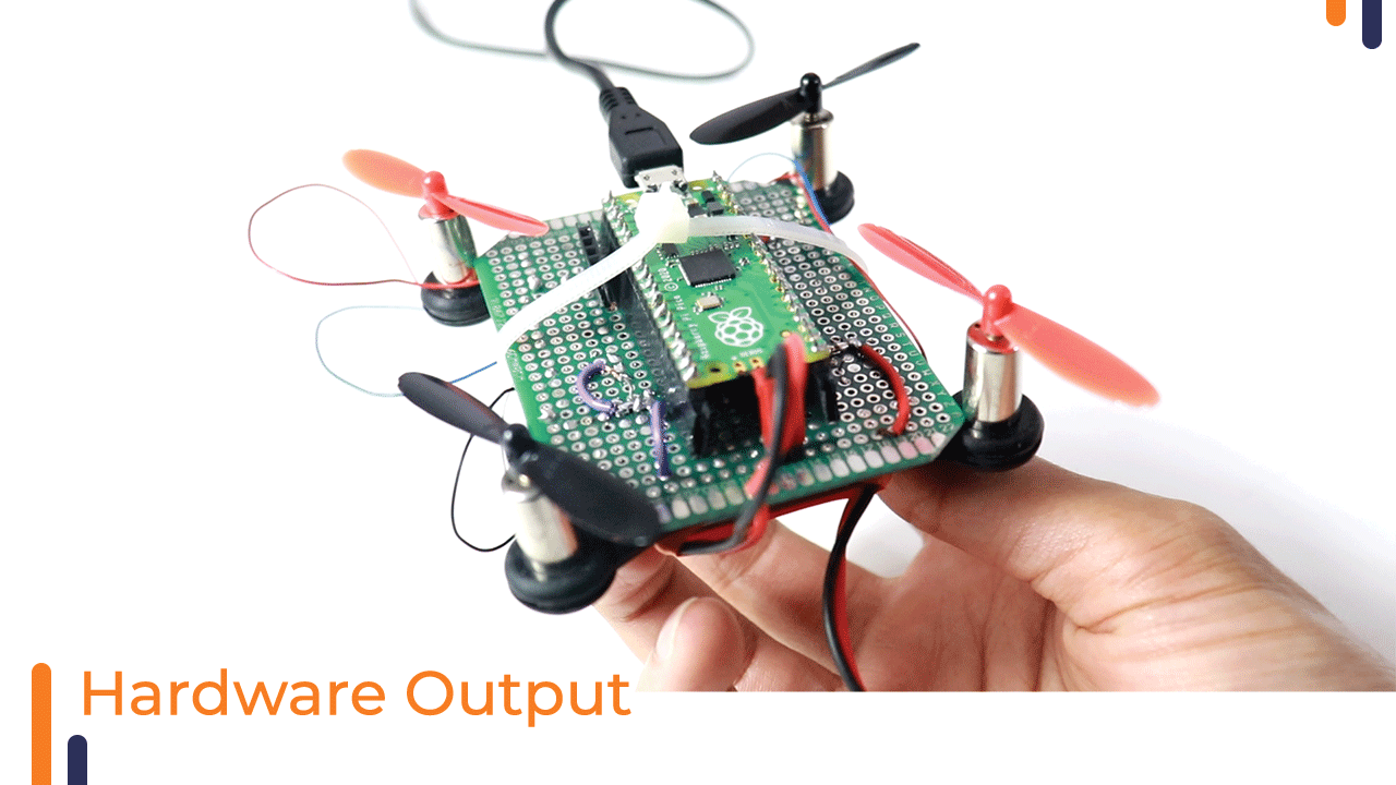
This is how our final output will somewhat look like.
Before understanding the various sections about building a drone, let’s understand the components we have chosen to build it.
Components
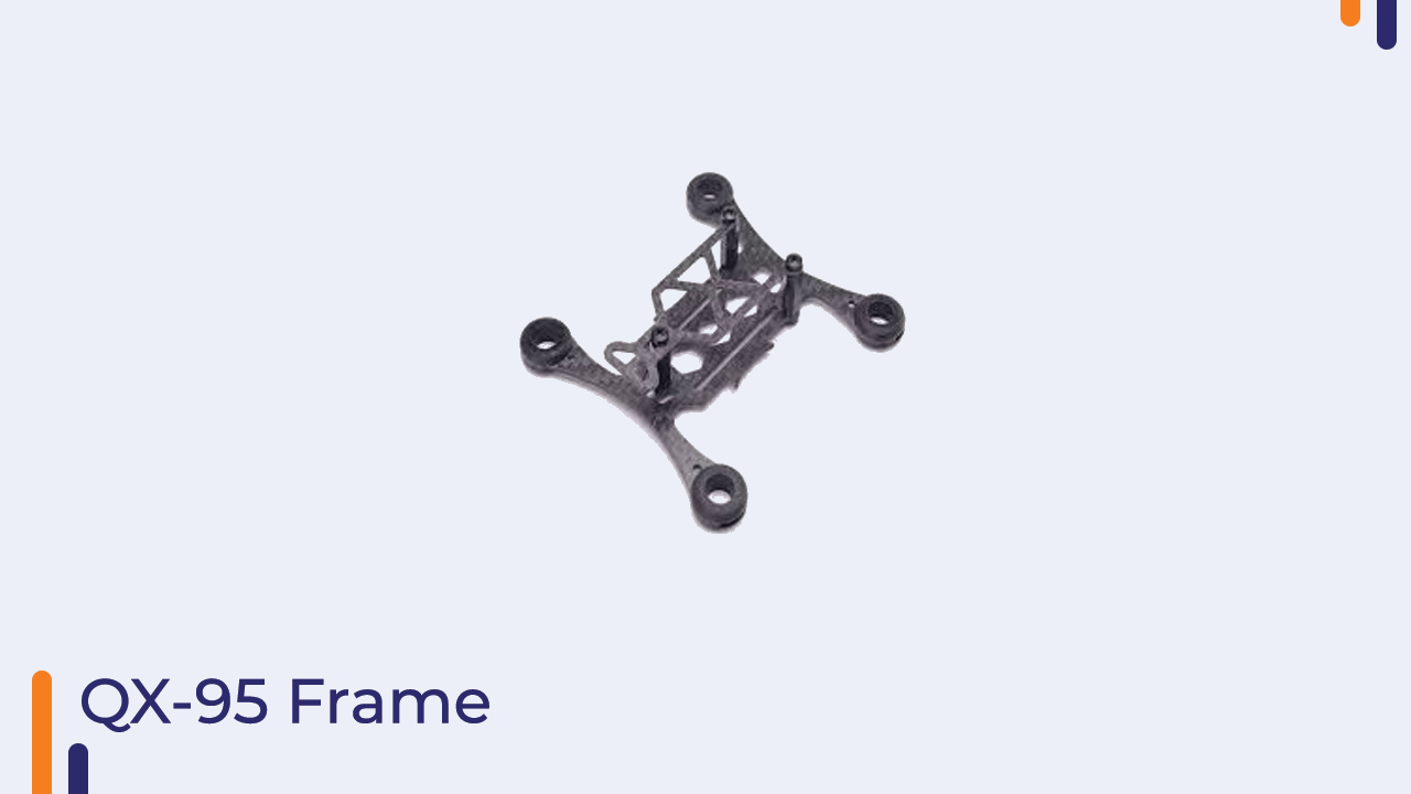
1)Frame: -The frame, motors, and propellers of this drone have been taken from the Qx95 kit available at robu.in.You can choose the frame of your choice too or better design it and 3d print it through robu.in’s 3d printing service.
When designing the frame there are a couple of considerations to make. The frame must be:
- Light – obviously the lighter it is, the easier it will be to lift it up!
- Sturdy – quadcopter tend to fall a lot and if it doesn’t break after every fall – is it a huge plus.
- Resistive to vibrations – otherwise it might be unstable as the motors do vibrate a lot. This also helps to reduce accelerometer picked up noise
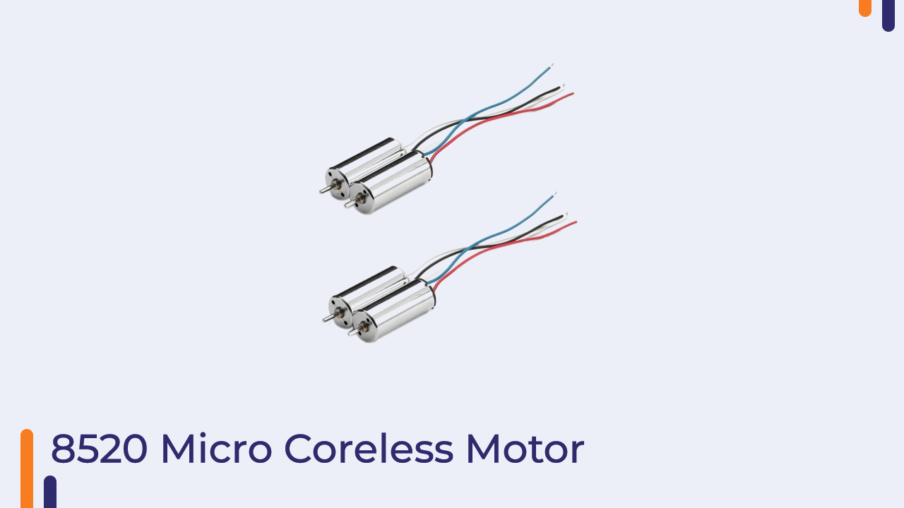
2)Motors:-
When buying motor sets the most important things (from most to less important) which you need to take a look at are:
- Type – there are brushed DC and brushless AC motors. Nano quadcopters are usually based on brushed DC motors as they’re smaller and easier to control without the need of extra AC controllers. However they have a lot less thrust and cannot be used for larger quadcopters.
- Can diameter – the 3D design was made for motors with 8.5mm diameter. The design would have to be altered for a different diameter.
- Max Static Thrust or simply Thrust – defines how much weight can the motors keep in the air or basically – how heavy your quadcopter can be. Propeller type have to be defined and often thrust vs current curve (often called performance curve) is supplied .
- Weight – the weight of a motor, which will be added to the total weight of the quadcopter. Both MMW and Hubson motors weight around 5g per motor.
- Load current – defines what current is being drawn by a motor when a specified voltage applied using specified propellers. Note that without the propellers attached this current would drop to really small values, thus when testing for brownout voltage (more of that later) always put on the propellers.
- Recommended propeller size – motors should aim for 55mm propellers.
- Lifetime rating – this defines how long should the motors run without failing. Thus always a good idea to buy two sets of motors.
- Speed – fast speed will give you faster flights, however with increased currents, thus need better batteries. Plus they’re likely more difficult to control due to their speed… Thus I wouldn’t care about this one for as long as the motors are designed for quadcopters.
3)Propellers:-
The propellers are differentiated by their:
- Length – which is measured as the radius multiplied by 2.
- Number of the leaves – this usually is 2, but others exist with 3 and more.
- Shape of the propeller –
- Angle of the twist – the steeper the angle, the more thrust the propeller can provide.

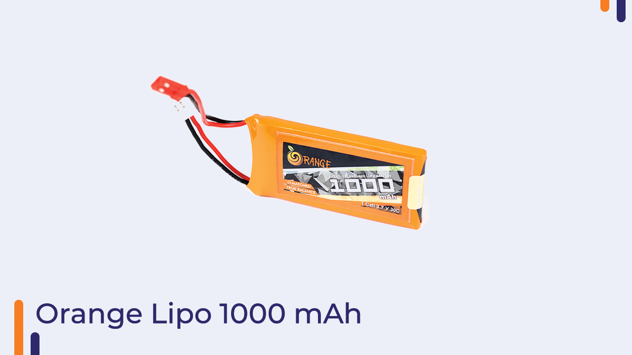
4)Battery
Choosing adequate batteries is very important as wrong batteries will not allow the motors to draw enough current to light up the quadcopter and on top of that, there will be huge voltage drops, which will keep interfering with the electronics. There are a few important points to note when buying them:
- Type – there are many battery types such as li-po, li-on and even these come in shades. Rather recently Graphene based batteries became available, which can withstand higher currents and have higher capacity density. Of course the downside is the price!
- Capacity (measured in mAh or Wh) – will determine how much energy is stored inside the battery. The larger the capacity, the longer the quadcopter will run on a single charge. This will be proportional to the size and weight of the battery and will also determine how much current can be drawn from and into the battery.
- Max allowed discharge (burst) and average discharge (constant) rate (C) – the first determines peak currents e.g. when quadcopter starts accelerating, while the latter determines normal operation current e.g. quadcopter is kept constant in the air. There is often a rule of thumb that multiplication of capacity and the discharge rate will give the current that the batteries can supply. To be on the safe side also need to add 20% of safety margin – we do not want the batteries to explode do we? Thus for example, if you had a battery with 200 mAh and 20 C of average/constant discharge, then 200mAh * 25C * 80% = 4A. Thus on average such a battery can supply 4A without issues. However, this is just a rule of thumb, when very high currents are involved, we want the discharge rate to be way higher, independently to the battery capacity.
- Weight (g) – larger capacity batteries weight more, thus need to find some which provide enough flying time but still provide good flying performance.
4)N-channel MOSFETs:-
We need 4xMOSFET transistors also known as switches. They will be used together with PWM to supply the current to the motors in peaks. Choosing them might be tricky and there are a couple of important points when choosing one for our application:
- Maximum drain current it can supply (Id max), which in this case should be around 3A to support the motor which can draw around 2.75A.
- The Vgs threshold voltage, which has to be low, maybe somewhere around 1V as li-po batteries voltage might drop to 3.4V at some point. If too large threshold is chosen raspberry pi pico won’t be able to turn the MOSFETs on enough to supply the required amount of current. It is always best to also check the drain current (Id) dependency on the threshold voltage (Vgs threshold) as each transistor will have a different response.
- Drain to sink resistance when MOSFET is fully turned on (Rds (on)). This is provided under certain gate to sink bias Vgs. Normally expect this to be around 0.032Ohm, however the smaller the better. If you choose some MOSFET with Rds (on) equal to 0.3Ohm or so, due to motors running at 3A the voltage drop over the MOSFET will be 0.9V, thus motors will not get sufficient voltage drop over them.
- I have used si 2302 n-channel mosfets in my circuit as it fulfilled all these requirements.

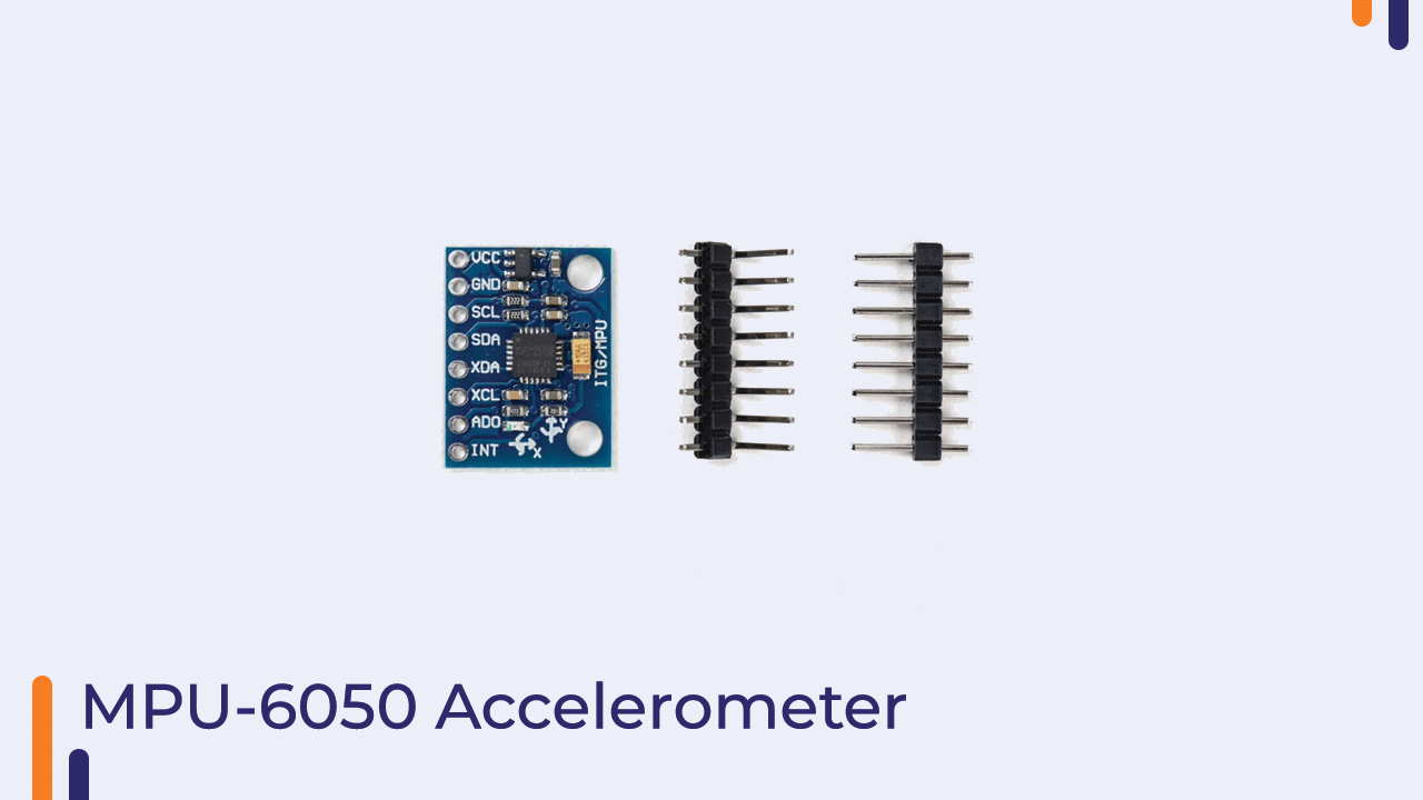
5) MPU6050 Accelerometer:-
When only using IMU to control the quadcopter two tricky problems appear:
- Being able to hover at a constant altitude. Usually the control of the Z axis (vertical) is done by increasing or decreasing the desired speed of all the motors, thus effectively adding offset. However due to the drained batteries throughout the flight even though the desired speed might not change, the voltage on the battery will drop, which will drop the speed.
- Automatic taking off and landing without the user interaction. This is useful both controlling the quadcopter as usual and when performing emergency landing in case of dying batteries. After the quadcopter reaches the land this can also be used to turn the motors completely off.
- I have used the Mpu6050 accelerometer for our multirotor as it seemed to be the most feasible of all.
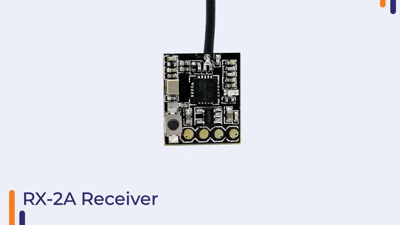
6) Rx2A receiver:- I have used the RX2A receiver as its size was very less and the benefit of using the I-bus protocol on it was a plus point for me.
Dividing into sections.
The pico flight controller is divided into 3 main sections.
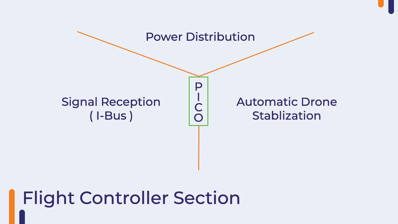
1)Power distribution section:-This section consists of n channel MOSFET which will receive the PWM signals on its gate terminal from the raspberry pi pico. the MOSFET will be used as a switch to turn the motor and off with the help of these signals.

The output of running motors will look something like this.
2)Signal reception section:-The Signal reception section consists of getting data from the transmitter through Ibus protocol. The FlySky iBus is a protocol that uses the UART serial interface to transmit the value of each channel from the receiver. Data is transmitted at 115200bps and a new value can be read every 7ms. The data then received will be converted into hexadecimal form.
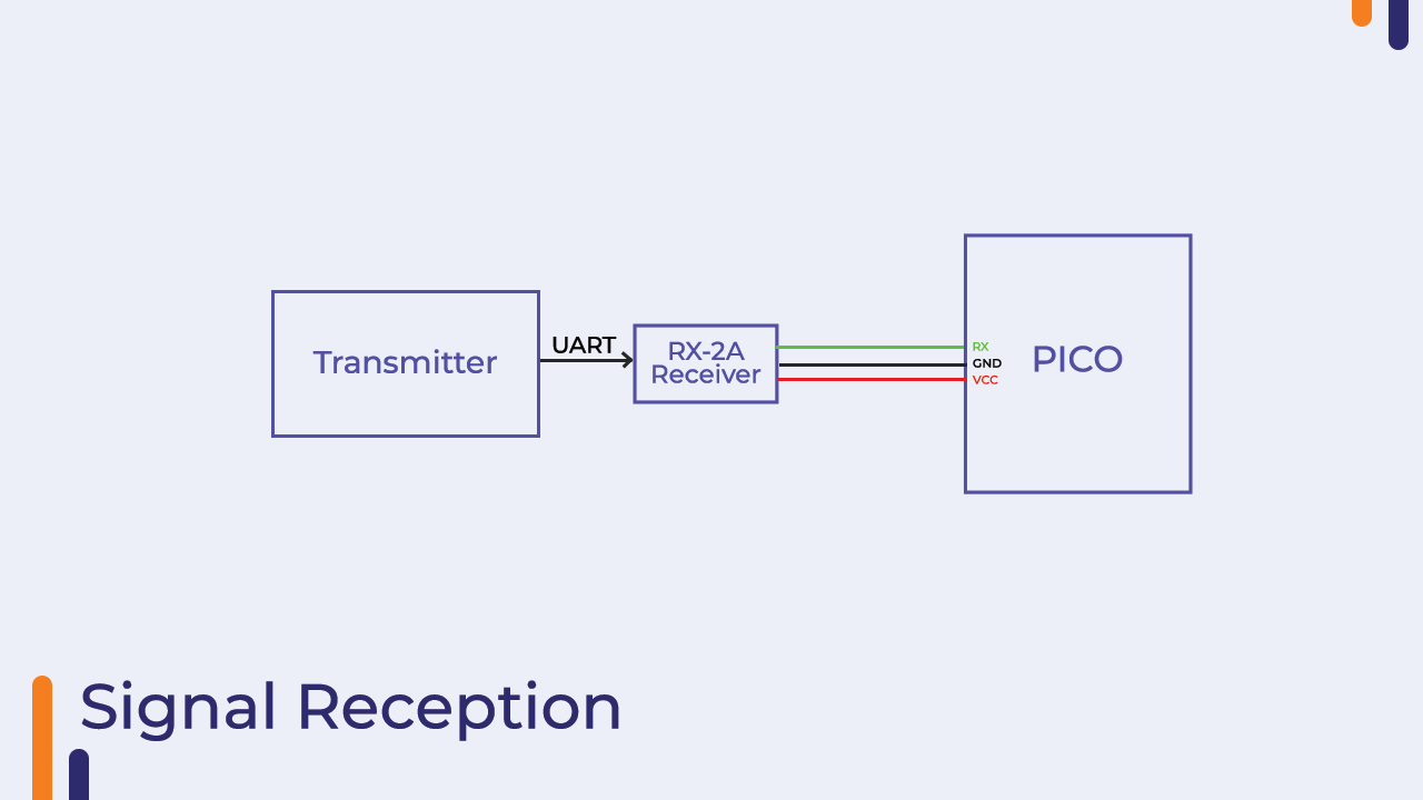
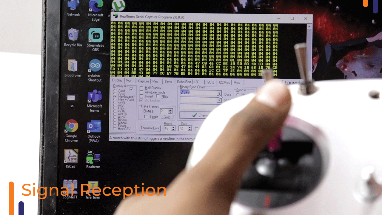
The output for the signal received from the transmitter is as follows.The output will be received in ascii form which you will need to convert in hex to make it processable.
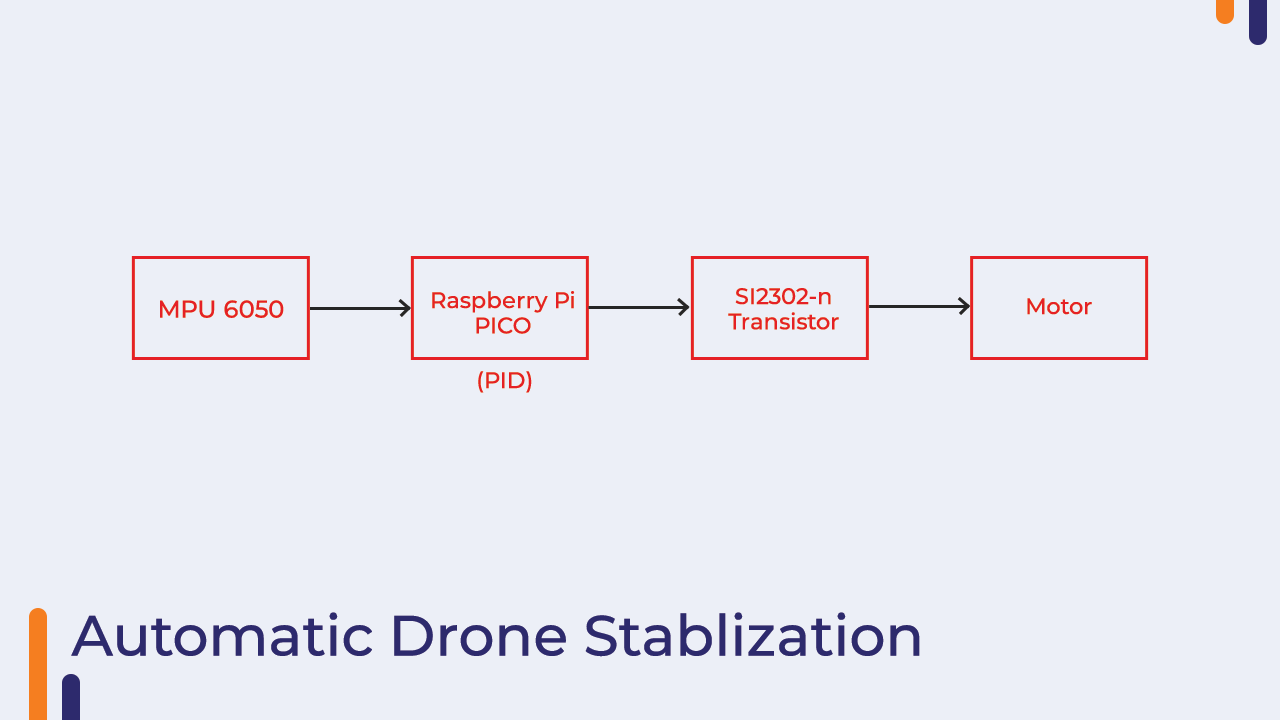
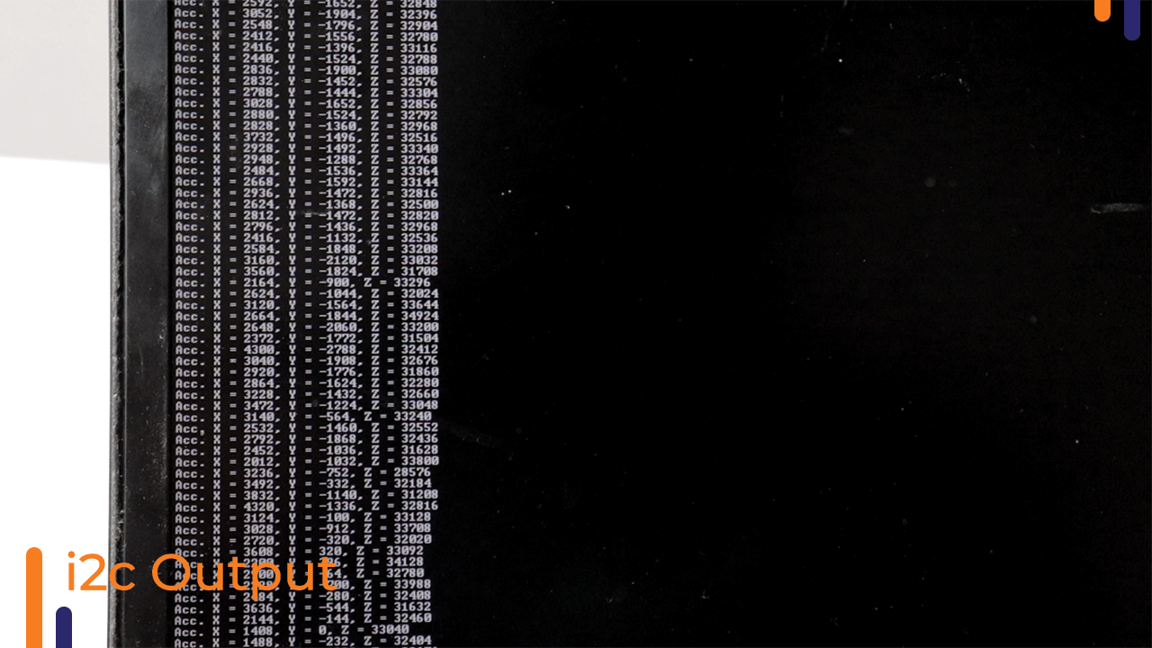
3)Automatic drone stabilization:-The basic idea behind this section is receiving the acceleration and gyroscopic values of MPU6050 using I2c protocol and then showing it on a terminal. The further process will be to process these values through PID to achieve complete drone stabilization.
The output for the mpu6050 accelerometer will be as follows.
We will be combining all the software together in the next part of this blog- the software section and test our drone.
You can watch our youtube video for more info. Thanks for reading this blog.
Stay safe. Stay tuned.