Transmitters and receivers have always been important for Rc hobbyists and engineers to control their projects. In this blog, you will be learning how you can build a 6 channel transmitter for yourself and control your Rc planes, Cars, and robots.
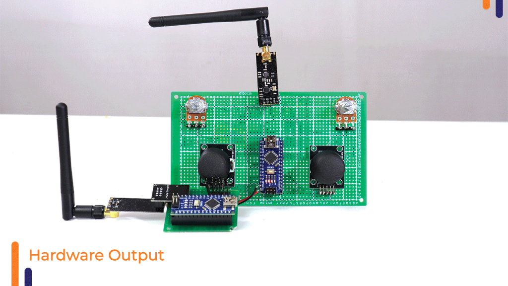
The output of our project will look something like this.

The components we used for building this project are:-
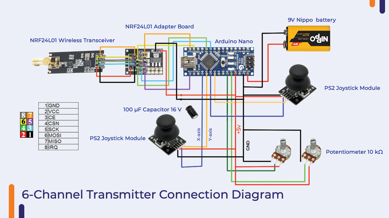
1. Arduino Nano x 2:- This will be our central microcontroller.

2. NRF24L01 Wireless Transceiver X 2:- The most important reason for choosing this module was its range which is close to 500m. The second reason was that while many other RF modules have a delay while speed, the reception time in NRF modules is instant.
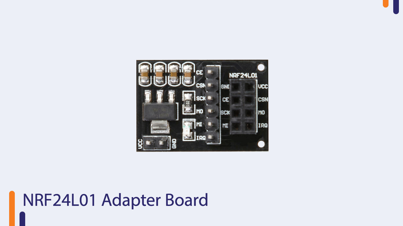
3. Adapter Board for NRF24L01 Wireless Module x 2:-The NRF module operates on a 3.3V power supply while the Arduino supplies both 3.3V and 5V.
There are two ways in which people generally connect the Arduino with the NRF module.
- 3.3V power supply of arduino directly connected to Vcc of NRF with a 100 μF capacitor in between.
- Use a readymade adapter board module in between the arduino and NRF module.
I tried both of these methods separately and discovered that I got the best results when i used both the capacitor and adapter together.
4. PS2 Joystick Module X 2:-The joystick consists of X-axis and Y-axis signal pins -these pins give analog signals as output, so you can connect them directly to any analog pins of Arduino.

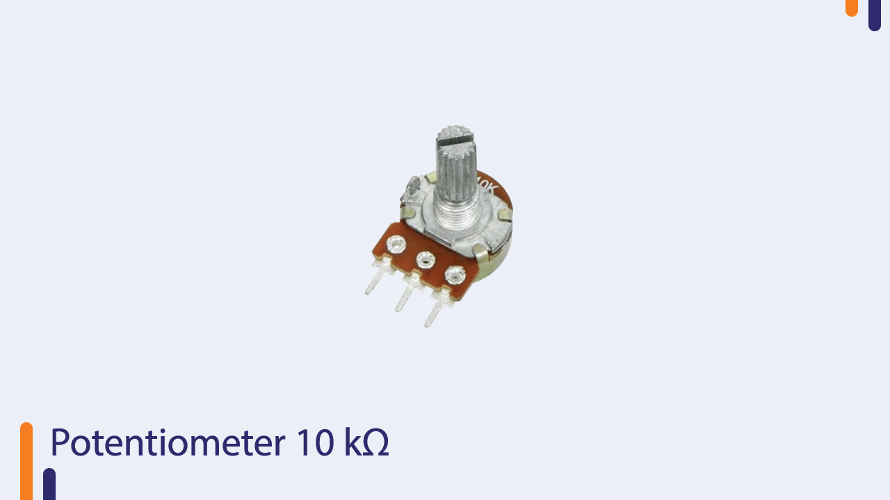
5. Potentiometer 10 kΩ x 2:- Similar to joystick module. It gives an analog input and can be connected to any Arduino analog input pin (A0-A5).
6. 100 μF Capacitor (16 V or above) x 2:- Used as a voltage noise filter for the transmitter and also to compensate for the additional current requirements for the NRF module.

7. 9V Nippo battery x 1:- It was used as a power supply as it was portable and had enough juice to send data properly to the receiver.

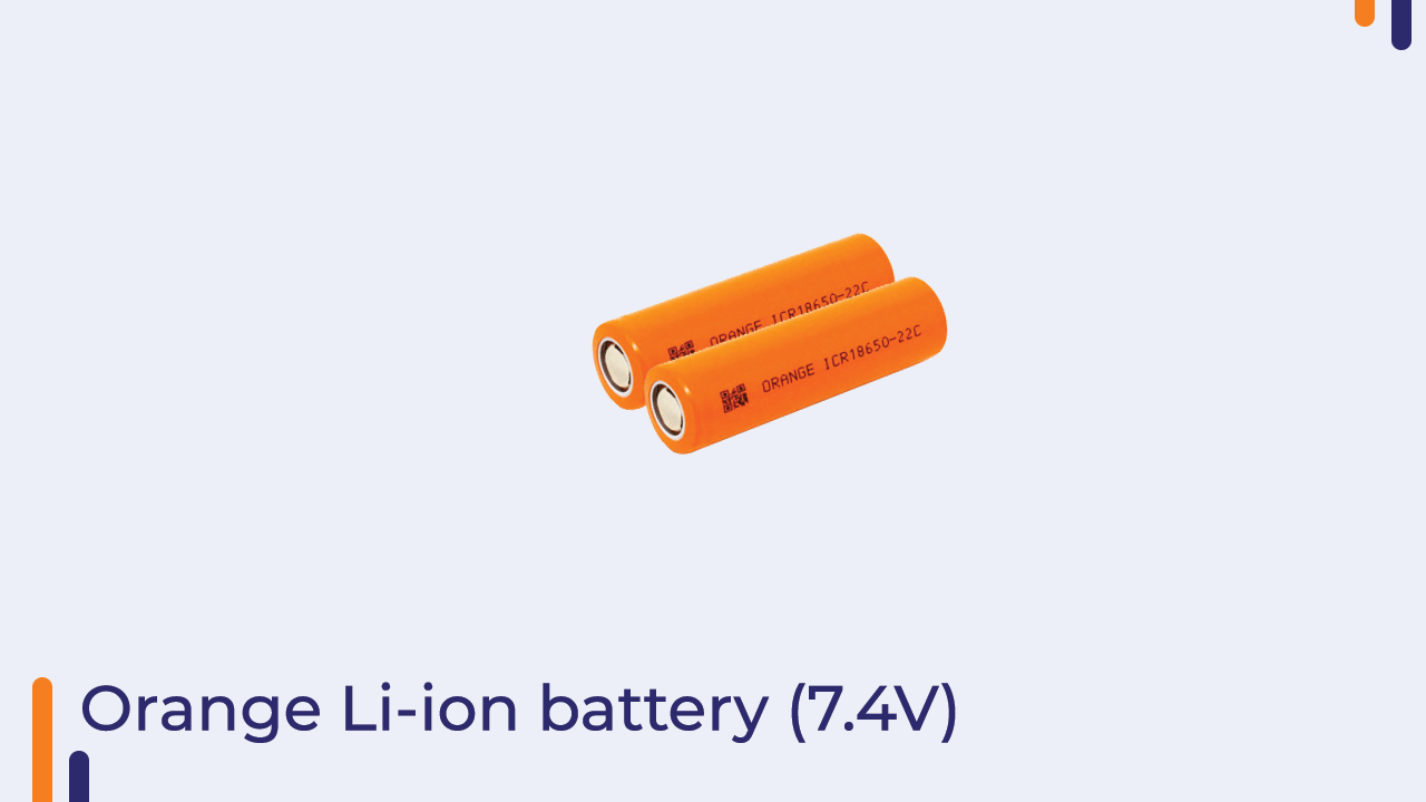
8. Orange Li-ion battery (7.4V) X 1:- The Orange Li-Ion batteries are used in order to power all the motors and the Arduino.
Transmitter circuit
Transmitter code
 #include <SPI.h>
  #include <nRF24L01.h>
  #include <RF24.h>

  RF24 radio(7, 8); // select CE,CSN pin
  const byte address[6] = "00001";
  struct Signal {
  byte throttle;
  byte pitch;
  byte roll;
  byte yaw;
  byte aux1;
  byte aux2;
};
  Signal data;

  void ResetData()
{
  data.throttle = 127;   // Default position of motors
  data.pitch = 127;
  data.roll = 127;
  data.yaw = 127;
  data.aux1 = 127;
  data.aux2 = 127;
}
  void setup()
{
  Serial.begin(9600);
  //Start everything up
  radio.begin();
  radio.openWritingPipe(address);
  radio.stopListening(); //start the radio comunication for Transmitter

}
  // Joystick center and its borders
  int mapJoystickValues(int val, int lower, int middle, int upper, bool reverse)
{
  val = constrain(val, lower, upper);
  if ( val < middle )
  val = map(val, lower, middle, 0, 128);
  else
  val = map(val, middle, upper, 128, 255);
  return ( reverse ? 255 - val : val );
}
  void loop()
{
  ResetData();
  // Control Stick Calibration
  // Setting may be required for the correct values of the control levers.
  data.throttle = mapJoystickValues( analogRead(A0), 12, 524, 1020, true );  // "true" or "false" for signal direction
  data.roll = mapJoystickValues( analogRead(A3), 12, 524, 1020, true );      // "true" or "false" for servo direction
  data.pitch = mapJoystickValues( analogRead(A2), 12, 524, 1020, true );     // "true" or "false" for servo direction
  data.yaw = mapJoystickValues( analogRead(A1), 12, 524, 1020, true );       // "true" or "false" for servo direction
  data.aux1 = mapJoystickValues( analogRead(A4), 12, 524, 1020, true );     // "true" or "false" for servo direction
  data.aux2 = mapJoystickValues( analogRead(A5), 12, 524, 1020, true );// "true" or "false" for servo direction
  Serial.print(data.throttle);
  Serial.print('t');
  Serial.print(data.roll);
  Serial.print('t');
  Serial.print(data.pitch);
  Serial.print('t');
  Serial.print(data.yaw);
  Serial.print('t');
  Serial.print(data.aux1);
  Serial.print('t');
  Serial.print(data.aux2);
  Serial.println('t');

  radio.write(&data, sizeof(Signal));
}
Receiver circuit
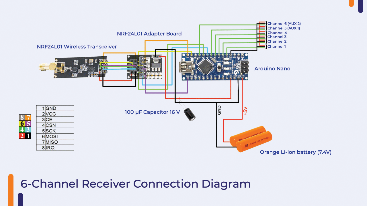
Receiver code
#include <SPI.h>
#include <nRF24L01.h>
#include <RF24.h>
#include <Servo.h>
int ch_width_1 = 0;
int ch_width_2 = 0;
int ch_width_3 = 0;
int ch_width_4 = 0;
int ch_width_5 = 0;
int ch_width_6 = 0;
Servo ch1;
Servo ch2;
Servo ch3;
Servo ch4;
Servo ch5;
Servo ch6;
struct Signal {
byte throttle;
byte pitch;
byte roll;
byte yaw;
byte aux1;
byte aux2;
};
Signal data;

RF24 radio(7, 8);
const byte address[6] = "00001";
void ResetData()
{
// Define the inicial value of each data input.
// The middle position for Potenciometers. (254/2=127)
data.roll = 127;
data.pitch = 127;
data.throttle = 127;
data.yaw = 127;
data.aux1 = 127;
data.aux2 = 127;
}
void setup()
{
  Serial.begin(9600);
  //Set the pins for each PWM signal
  ch1.attach(2);
  ch2.attach(3);
  ch3.attach(4);
  ch4.attach(5);
  ch5.attach(6);
  //Configure the NRF24 module
  ResetData();
  radio.begin();
  radio.openReadingPipe(0, address);
  radio.startListening(); //start the radio comunication for receiver
}
unsigned long lastRecvTime = 0;
void recvData()
{
if ( radio.available() ) {
radio.read(&data, sizeof(Signal));
lastRecvTime = millis();   // receive the data | data alınıyor
}
}
void loop()
{
recvData();
unsigned long now = millis();
if ( now - lastRecvTime > 1000 ) {
ResetData(); // Signal lost.. Reset data
}
ch_width_4 = map(data.yaw,      0, 255, 1000, 2000);     // pin D5 (PWM signal)
ch_width_2 = map(data.pitch,    0, 255, 1000, 2000);     // pin D3 (PWM signal)
ch_width_3 = map(data.throttle, 0, 255, 1000, 2000);     // pin D4 (PWM signal)
ch_width_1 = map(data.roll,     0, 255, 1000, 2000);     // pin D2 (PWM signal)
ch_width_5 = map(data.aux1,     0, 255, 1000, 2000);     // pin D6 (PWM signal)
ch_width_6 = map(data.aux2,     0, 255, 1000, 2000);     // pin D7 (PWM signal)
Serial.print(ch_width_1+2);
Serial.print('t');

Serial.print(ch_width_2);
Serial.print('t');
Serial.print(ch_width_3);
Serial.print('t');
Serial.print(ch_width_4);
Serial.print('t');
Serial.print(ch_width_5);
Serial.print('t');
Serial.println(ch_width_6);
// Write the PWM signal
ch1.writeMicroseconds(ch_width_1);
ch2.writeMicroseconds(ch_width_2);
ch3.writeMicroseconds(ch_width_3);
ch4.writeMicroseconds(ch_width_4);
ch5.writeMicroseconds(ch_width_5);
ch6.writeMicroseconds(ch_width_6);
}
If you’ve reached the end. It means that you’ve read the whole thing.
I will be trying to make a v2 of this transmitter with a Display (LED or LCD) and add a few more channels -up to 10 or more. let me know in the comment section if we should do that.
You can watch our youtube video for more info.
Thank you for your time. Stay safe. Stay tuned.