Hello Geek, In this blog, we will talk about the Orange 37 in 1 sensor kit. This kit is compatible with all microcontrollers and microprocessors.
The only concern is the power supply. The sensor you get with this kit has an operating voltage of 5v.
If your controller does not support 5V input voltage, I recommend using a voltage level converter or a resistor divider circuit.
If you haven’t purchased any Arduino board yet, we request you to buy an Arduino board from here.
The components included in this kit are listed in the table below.
Please have a look at it.
Orange 37 in 1 Sensor Kit Components
| Sr No. | Components Name | Quantity |
|---|---|---|
| 1. | PS2 Game JoyStick Module | 1 |
| 2. | 1 Channel Relay 5V | 1 |
| 3. | Sound Sensor Module | 1 |
| 4. | Small Microphone Sound Sensor Module | 1 |
| 5. | TCRT5000 Tracking Module | 1 |
| 6. | IR Obstacle Avoidance Sensor Module | 1 |
| 7. | The Flame Sensor Module | 1 |
| 8. | Linear Magnetic Hall sensor | 1 |
| 9. | Touch Module | 1 |
| 10. | Digital Temperature Module | 1 |
| 11. | Active Buzzer Module | 1 |
| 12. | Passive Buzzer Module | 1 |
| 13. | DIP 3 Color LED Module | 1 |
| 14. | SMD 3 Color LED Module | 1 |
| 15. | 5mm Two-Color LED Module | 1 |
| 16. | 3mm Two-Color LED Module | 1 |
| 17. | Dry Reed Pipe Module | 1 |
| 18. | Mini Dry Reed Pipe Module | 1 |
| 19. | Finger Detecting Heartbeat Module | 1 |
| 20. | 7 Color Flashing LED Module | 1 |
| 21. | Laser Module | 1 |
| 22. | Tachile Switch Module | 1 |
| 23. | Vibration Switch Module | 1 |
| 24. | Blue Rotary Encoder Module for Arduino with Demo Code | 1 |
| 25. | Magic Cup Light Module | 1 |
| 26. | Mercury Medallion Module | 1 |
| 27. | Tilt Switch Module | 1 |
| 28. | Photosensitive Resistor Sensor Module | 1 |
| 29. | DHT11 Temperature and Humidity Sensor Module | 1 |
| 30. | Analog Hall Magnetic Sensors | 1 |
| 31. | Hall Magnetic Sensor Module | 1 |
| 32. | DS18B20 Temperature Sensor Module | 1 |
| 33 | Analog Temperature Module | 1 |
| 34 | Infrared Transmit Sensor Module | 1 |
| 35 | Infrared Receiver Module for Arduino | 1 |
| 36 | The Knock Sensor Module | 1 |
| 37 | Broken Light Module | 1 |
So that was the first part of the orange sensor kit’s introduction. In the next section of this blog, we’ll look at how these sensors work and how to connect them to an Arduino board.
Hall Effect Sensor – Orange 37 in 1 Sensor Kit
With this Orange 37 in 1 sensor kit, you are getting three types of hall effect sensors. The working principle of those three sensors is the same but the output of those sensors is slightly different.
The hall effect sensors we are getting with this kit are as follows:
1. Linear Hall Effect Sensor
2. Switch Hall Effect Sensor
3. Hall Effect Sensor with Differential Amplifier
These are the three types of sensors that you are getting with this orange 37 in 1 sensor kit.
If we talk about the output type of these sensors, then the output of the linear hall effect sensor is analogue and the output of the switch hall effect sensor is digital.
Talking about the third hall effect sensor, we get two types of output; analog output and digital output in that sensor.
This was about the hall effect sensor that we are getting with this kit.
In the next part of this blog, we will talk about interfacing the Hall Effect sensors with Arduino.
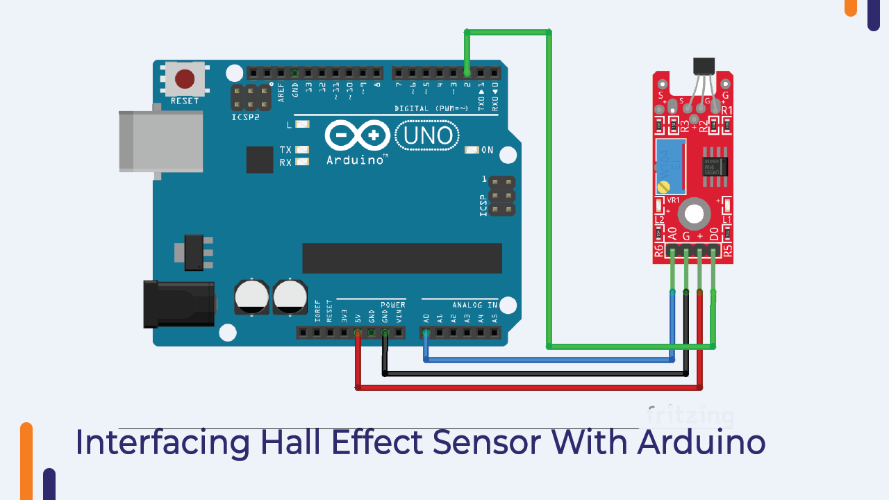
Interfacing of The Hall Effect sensor With The Arduino:
You will need the following components to understand the working of the Hall Effect sensor.
Components List
- Connecting Cable
- Arduino Board
- 5v Power Supply
- Breadboard
As I told you earlier that the working of these three hall sensors is the same, the only difference is that the output type of these sensors is different.
So, we have to make the connection according to the output type of the sensor.
I have shared the connection diagrams below, please have a look and if you have any doubts please let us know in the comment section.
Arduino Code For Orange Kit Hall Effect Sensor
Programming for the Orange Kit Hall Effect sensor is very easy. Since the output of these sensors can be either digital or analog, we just need to connect the signal pin of the sensor to the correct GPIO pin of the Arduino.
If you are using a linear Hall sensor or a number third sensor, you will need to connect the signal pin of that sensor to the analog pin of the Arduino.
There are four pins on sensor number three, two of which are signal pins.
On those pins, you’ll find the sensor outputs.
All of those two pins do not need to be connected to Arduino. To use this sensor with the Arduino, simply connect the analog or digital pin to the arduino.
The PIN you choose will be determined by the requirements of your application.
If your application requires analog reading from the sensor then you can connect the hall effect sensor’s analog output pin to Arduino and if your application requires the sensor’s digital output as input then you can connect the sensor’s digital pin to Arduino.
Talking about the switch type of Hall Effect sensor, the output type of this sensor is digital. So we can connect this pin to any digital GPIO pin of Arduino.
So, it was about the interfacing diagram of hall effect sensor. I have shared the interfacing diagram in the image below, please have a look, and if any doubt please ask me in the comment section.
Code Explanation
Since the output type of the sensor will be either analog or digital, we can use either the analog read or digital read function to read the output of the sensor.
I have shared two code snippets below; One code snippet is for detecting analog output and the other is for digital output.
You can use either of these two snippets as per your application requirement.
If you face any problem then you can tell your problem in comment section.
const int hall_Sensor = 2;
int inputVal = A1;

void setup()
{
  pinMode(13, OUTPUT);          // Pin 13 has an LED connected on most Arduino boards:
  pinMode(hall_Sensor,INPUT);    //Pin 2 is connected to the output of proximity sensor
  Serial.begin(9600);
}

void loop()
{
  if(digitalRead(hall_Sensor)==HIGH)      //Check the sensor output
  {
    digitalWrite(13, HIGH);   // set the LED on
  }
  else
  {
    digitalWrite(13, LOW);    // set the LED off
  }
inputVal = digitalRead(hall_Sensor);
Serial.println(inputVal);
delay(1000);              // wait for a second
}
volatile byte half_revolutions;
 unsigned int rpm;
 unsigned long timeold;
 void setup()
 {
   Serial.begin(115200);
   attachInterrupt(0, magnet_detect, RISING);//Initialize the intterrupt pin (Arduino digital pin 2)
   half_revolutions = 0;
   rpm = 0;
   timeold = 0;
 }
 void loop()//Measure RPM
 {
   if (half_revolutions >= 20) {
     rpm = 30*1000/(millis() - timeold)*half_revolutions;
     timeold = millis();
     half_revolutions = 0;
     //Serial.println(rpm,DEC);
   }
 }
 void magnet_detect()//This function is called whenever a magnet/interrupt is detected by the arduino
 {
   half_revolutions++;
   Serial.println("detect");
 }
So, this was about the Hall Effect sensor that we are getting with the Orange 37 in 1 sensor kit. In the next section, we’ll talk about the PS2 joystick.
PS2 Joystick
We all used joysticks in our childhood. The kind of Super Mario games we used to play when we were kids was controlled by a joystick controller. Plus, the electronic toy cars you used to play with as a child were controlled by joysticks.
So, as you have already used the joystick, it will be very easy for you to understand the working of the joystick.
The joystick has two potentiometers. When we move the joystick, the position of the potentiometer changes.
A change in the position of the potentiometer means that the resistance of the potentiometer changes. Therefore, as the resistance is changing, the output voltage of the potentiometer also changes.
The output of those potentiometers is connected to the microcontroller. When the microcontroller receives input from those potentiometers, the microcontroller takes further necessary action based on the logic that you have added to your code.
If you want to understand the working of joystick then I request you to refer its manual. I have mentioned everything about this kit there.
<<<<<<<<Link>>>>>>>>
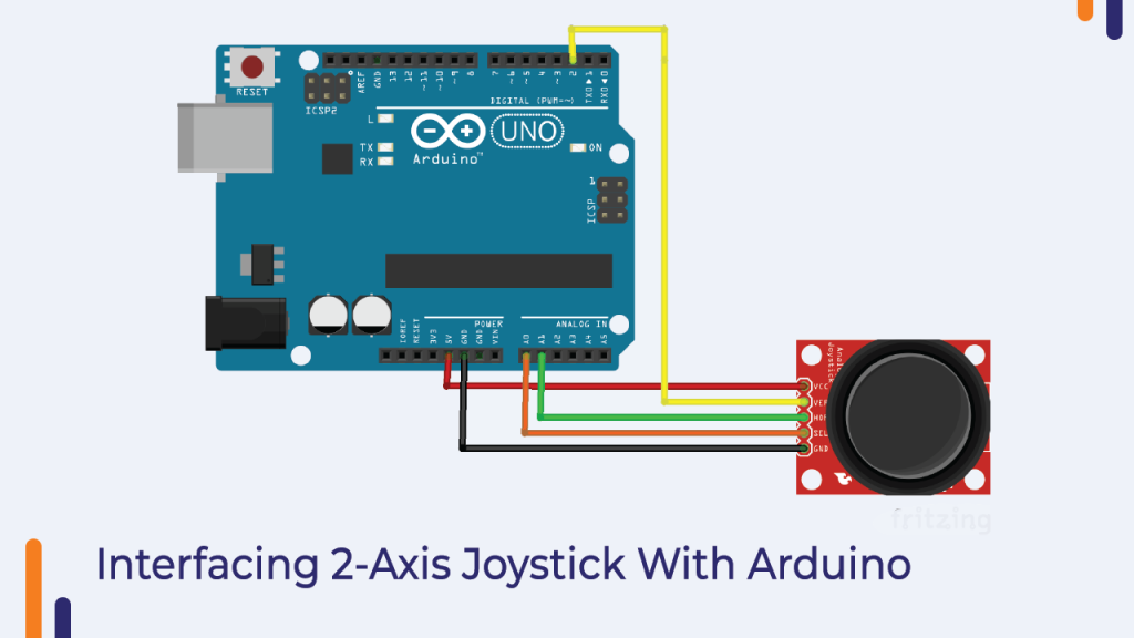
Coming back to our discussion, that joystick module has four output pins. We will discuss more about the interfacing diagram and the pin functions in the below section.
Interfacing the Joystick Module With the Arduino
You will need the following components to understand the function of the joystick.
Component List
- Arduino Board
- Connecting Cables
- Breadboard
In this section, I have explained the function of those pins in the below section, please have a look.
- X – This pin generates the analog output voltage. (0-255) and is used to monitor the movement of the joystick on the X-plane.
- Y – This pin also generates the analog output voltage and is used to monitor the movement of the joystick on the Y-plane.
- Switch – This pin is the output of the switch placed under the joystick. When we press the joystick, this pin generates high voltage. Sometimes this switch is also used to locate the Z-axis of the joystick.
Now that you know the function of each pin, we can now connect them to the Arduino.
Analog pin of module pin ‘X’ and pin ‘Y’ You can connect the analog pin of Arduino and the digital pin of the module to the digital pin of the Arduino.
Please refer to the following image to understand the connection diagram.

Arduino Code For Joystick Module
The joystick’s output is either analog or digital. Therefore, we can use analog read and digital read functions to read the output.
Since the joystick’s output is in a simple format, we don’t need to install any libraries to work with this board, the normal analog read function and digital read function will work for the application.
In the following code, we have not used any library. We have used a variable to store the value of the sensor and that value we are printing on the serial monitor using serial. print method.
It was about joystick code. If you have any doubts regarding the code then you can mention your doubts in the comment section.
#define joyX A0
#define joyY A1

int button=2;
int buttonState = 0;
int buttonState1 = 0;

void setup() {
  pinMode(7,OUTPUT);
  pinMode(button,INPUT);
  digitalWrite(button, HIGH);
  Serial.begin(9600);
}

void loop() {
 int xValue = analogRead(joyX);
 int yValue = analogRead(joyY);
 int button_output = digitalRead(button);

  Serial.print(xValue);
  Serial.print("t");
  Serial.print(yValue);
  Serial.print("t");
  Serial.println(button_output);

}
Photo Resister Sensor
Photoresistor sensors are sensors designed to detect light. These sensors are nothing but a resistor. When the intensity of the light changes, the resistance of this sensor varies.
So, to measure the intensity of light, we have to measure the resistance of the sensor and we can use Ohm’s law to measure the resistance.
These sensors are also known as Light Dependent Resistors (LDR).
This was about the introduction of LDR sensor, in the next part of this blog we will learn about how to interface LDR with Arduino.
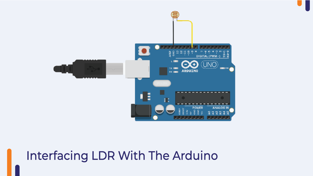
Interfacing LDR With Arduino
The photosensor we get with this module has three GPIO pins. The function of those pins is as follows.
GND – Here you can connect the GND pin of the Arduino.
Vcc – The VCC pin of the Arduino must be connected to this pin.
Signal – On this pin we will get the output of the sensor. This pin should be connected to the analog pin of the Arduino.
It was about the pin configuration of the sensor. Now we will understand about the interfacing of the sensor with Arduino.
I have shared the connection diagram below; You can follow the following image to understand the connection diagram.
In the following image, you can see that we have connected the signal pin of the sensor to the analog pin of the Arduino and the power pin of the sensor to the power pin of the Arduino.
Please see the following image.
So as you have understood about the connection diagram now we can go ahead and start working on the coding part of the LDR(Photoresister) sensor.
LDR Arduino Code explanation
As I told you earlier, the LDR sensor is nothing but a resistor. So, since it is a resistor, we can use the analog read function to read the output of the module.
In the following code, I have used analog read function to read the output of the sensor and we are displaying the output on the serial monitor.
To check the output of the sensor you can upload the code to your Arduino and see the output on the serial monitor.
int LDR = A0;
int LED = 7;
void setup()
{
  // put your setup code here, to run once:
  pinMode(LDR, INPUT);
  pinMode(LED, OUTPUT);
  Serial.begin(9600);

}

int LDRoutput = 0;
void loop()
{
  // put your main code here, to run repeatedly:
  LDRoutput = analogRead(LDR);
  if (LDRoutput < 30 )
  {
    digitalWrite(LED, HIGH);
    Serial.println("Moon Light!!");
  }
  else
  {
    Serial.println("Daylight");
    digitalWrite(LED, LOW);
  }

}
Common Cathode Two Color LED
We are getting the Common Cathode Color LED Module with Orange 37 in 1 Sensor Kit.
There are two LEDs in that module and the cathode terminal of those LEDs are interconnected and the anode terminal of the LED is left open.
You can see in the above image that you are getting one SMD package LED and one DIP package LED.
Now you know which LED you will be getting with this kit but do you know how the LED will produce different colors?
The LEDs that are installed inside this LED glass can be turned on one after the other or on the same.
And if we want to control the brightness of a particular LED then we have to convert the input voltage to that LED.
And to change the input voltage, we can use the PWM function.
PWM technology is a pulse width modulation technology. It is mainly used in audio amplifiers, motor controllers.
Here in the code below, we have used the same technique to control the brightness of the LED.
As I told you earlier, we can turn on both the LEDs at the same time or we can turn on each LED one after the other.
But before that, we will understand the interfacing of this LED with Arduino.
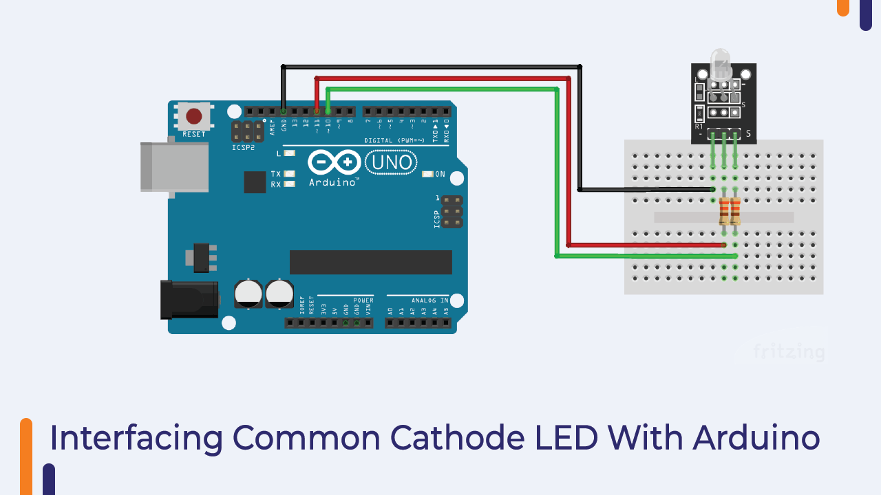
Interfacing Common Cathode LED with Arduino
I have explained the function of those pins below please have a look.
Cathode Pin – The cathode pins of both the LEDs are connected to this pin.
Anode Pin – This pin has three anode terminals. (RYB) You have to connect this pin to the 5V pin of the Arduino.
Note – The color of the LED may be different.
You can check the following image to understand the interfacing diagram properly.
In the following image, you can see that we have connected the anode terminals to the digital pins of the Arduino and the cathode terminals to GND.
The reason for connecting the LED to those pins is because those pins are PWM pins and as our application requires PWM functionality we have used them.
You can use any GPIO pin of the Arduino to turn on the LEDs but if you want to control the brightness of those LEDs you only need to use the PWM pins.
So, it was about interfacing the LED with the Arduino. In the next section, you will find the Arduino code to control the brightness of the LED.
Arduino code for common cathode LED
We have already talked about the technology that we are going to use to control the Common Cathode LED.
You can use the following code to control the brightness of the LED.
If you face any problem then you can tell your problem in the comment section.
int red_light_pin= 11;
int green_light_pin = 10;
int blue_light_pin = 9;
void setup() {
  pinMode(red_light_pin, OUTPUT);
  pinMode(green_light_pin, OUTPUT);
  pinMode(blue_light_pin, OUTPUT);
}
void loop() {
  RGB_color(255, 0, 0); // Red
  delay(1000);
  RGB_color(0, 255, 0); // Green
  delay(1000);
  RGB_color(0, 0, 255); // Blue
  delay(1000);
  RGB_color(255, 255, 125); // Raspberry
  delay(1000);
  RGB_color(0, 255, 255); // Cyan
  delay(1000);
  RGB_color(255, 0, 255); // Magenta
  delay(1000);
  RGB_color(255, 255, 0); // Yellow
  delay(1000);
  RGB_color(255, 255, 255); // White
  delay(1000);
}
void RGB_color(int red_light_value, int green_light_value, int blue_light_value)
 {
  analogWrite(red_light_pin, red_light_value);
  analogWrite(green_light_pin, green_light_value);
  analogWrite(blue_light_pin, blue_light_value);
}
RGB LED –
You may have used LEDs many times in your projects. In this kit, you are getting an LED but this LED is a little different from the normal LED. This LED produces three different colours.
I know you might be interested to know about the working of LED, in this section we will understand the working of RGB LED.
Before we talk about how RGB works, I would like to tell you the basics of RGB. So every colour you see around is made up of three primary colours.
Those three primary colours are as follows.
- Red
- Green
- Blue
And the following methods are used to create different types of colours.
- Additive Mixture
- Subtracting The Mixture
The following images show color mixing methods.

We are getting two different LEDs with the kit. The function of both these LEDs is the same but the only difference is that the packaging of the product is different.
Up until this point, we were talking about the colour mixing process of RGB LEDs, but do you know how RGB LEDs emit different colors?
RGB LED works on PWM value, when a variable voltage is applied to the input terminal of RGB LED, the LED starts emitting different colors.
So, we can say that the color of the LED depends on the PWM value that we are applying to the input pin of the LED.
We can generate PWM voltage by using analogWrite function. There are other ways to generate PWM voltage as well, we’ve talked about those methods in the kit’s manual.
You can check those methods there.
In the next part of this blog, we will talk about interfacing the sensor with Arduino.
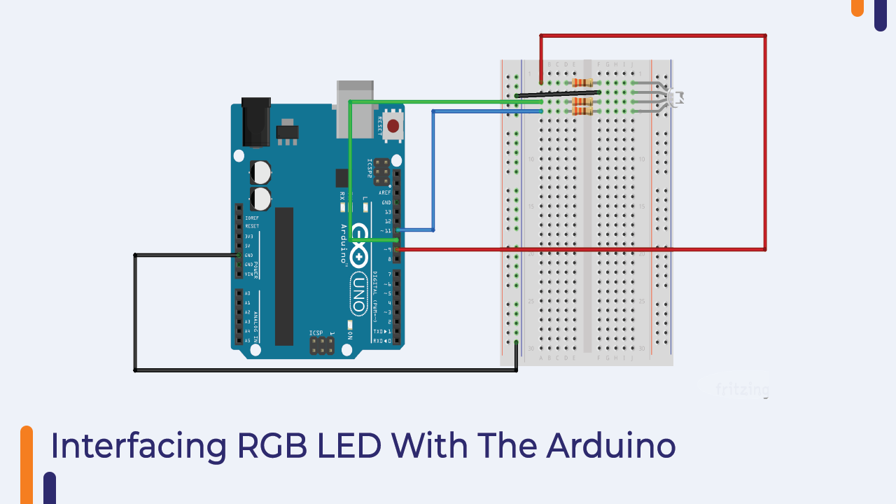
Interfacing RGB LEDs With Arduino
With this orange 37 in 1 sensor kit, you get an RGB LED, which only has three pins. VCC, GND and Signal.
To turn on the LED, you need to apply a PWM signal to the signal pin of the RGB LED.
In my case, I connected the signal pin of my RGB to the 9-number pin of the Arduino. and another power pin to the Arduino’s power pin.
You can check the following image to understand the interfacing diagram properly.
Arduino Code For RGB LED
As discussed in the previous sections, we have used the analog write function to write the PWM values.
You can use the following code and if you have any doubts please let us know in the comment section.
int red_light_pin= 11;
int green_light_pin = 10;
int blue_light_pin = 9;
void setup() {
  pinMode(red_light_pin, OUTPUT);
  pinMode(green_light_pin, OUTPUT);
  pinMode(blue_light_pin, OUTPUT);
}
void loop() {
  RGB_color(255, 0, 0); // Red
  delay(1000);
  RGB_color(0, 255, 0); // Green
  delay(1000);
  RGB_color(0, 0, 255); // Blue
  delay(1000);
  RGB_color(255, 255, 125); // Raspberry
  delay(1000);
  RGB_color(0, 255, 255); // Cyan
  delay(1000);
  RGB_color(255, 0, 255); // Magenta
  delay(1000);
  RGB_color(255, 255, 0); // Yellow
  delay(1000);
  RGB_color(255, 255, 255); // White
  delay(1000);
}
void RGB_color(int red_light_value, int green_light_value, int blue_light_value)
 {
  analogWrite(red_light_pin, red_light_value);
  analogWrite(green_light_pin, green_light_value);
  analogWrite(blue_light_pin, blue_light_value);
}
Shock Switch
This is the shock sensor that we are getting with this kit. Now, where do we use this sensor?
This sensor can be used in many applications such as shock sensor-based wake-up systems, toys and many other places.
But how does this sensor detect shocks? We are going to discuss about all those things in the below section.
So, the shock switch has two main parts. One is a thin metal coil and the other is a conductive material.
When the sensor moves a thin metal wire wrapped around the conductive material also moves and touches the conductive material.
When the coil touches the conductive material the voltage applied on the conductive material is transferred to the coil and we get the voltage at the other end of the coil.
The output of this sensor will be digital so we can use the digital read function to read the output of the sensor.
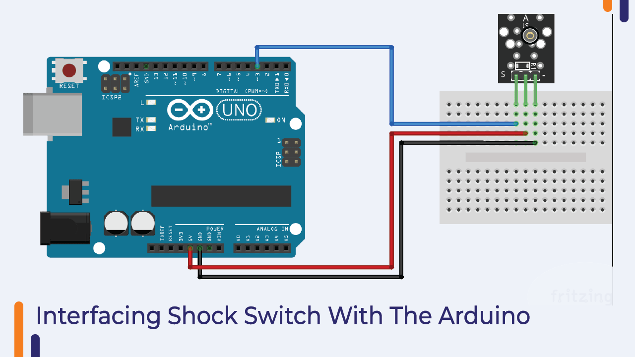
Interfacing Shock Switch With Arduino
The shock pin consists of three pins. Signal pins, VCC and GND pins. Signal pin of sensor We can connect any GPIO pin of Arduino and power pin of the sensor to the power pin of Arduino.
I have shared the images of both the methods. Please have a look and if you face any problem then you can mention your problem in the comment section.
Arduino Code For The Shock Sensor
In the below section, I have shared the code for Arduino. In this code, I am using the digitalRead function to read the output of the sensor.
You can use the following code and start working with the shock sensor.
In the following code, we are reading the output of the sensor and printing it to the serial monitor.
So, to check the output of the sensor you have to open the serial monitor.
int shockMin = 996;  //you might need to change these
int shockMax = 1010;  //you might need to change these
void setup() {
  pinMode(11, OUTPUT);
  // Serial.begin(9600); //uncomment this to help with calibration
}
void loop() {
  int shock = analogRead(A0);
  int lightval = map(shock, shockMin, shockMax, 0, 255);
  if (lightval > 0) {
    analogWrite(11, lightval);
  }
  else {
    analogWrite(11, 0);
  }
  // Serial.println(shock); //uncomment this to help with calibration
}
It was about the shock sensor. In the next part of this blog, we will understand about the knock sensor.
Knock Sensor:
The working principle of the knock sensor is the same as that of the shock sensor.
When we rotate this sensor, this sensor generates a high-level voltage signal.
It is used in doorbell applications and automatic switching boards.
The interfacing of these sensors is simple. In the next part of this blog, we will understand the interfacing of sensors with Arduino.
Interfacing Knock Sensor With Arduino
The interface of the knock sensor is slightly different from that of the shock sensor.
In interfacing the shock sensor with Arduino we were using a pull-up or pull-down resistors but in the case of the knock sensor, we do not need to add any external circuit.
In the following image, you can see that I have connected the sensor’s output to the Arduino and the sensor’s power pin to the Arduino’s power pin.
Please see the following image of the sensor to understand the working of the sensor.
Arduino Code For Knock Sensor
The following code is designed for the knock sensor. In this code, I have used digitalRead function to read the output of the sensor.
Please check the below code and if you have any doubt please let us know we will help you.
const int knockPin = 7;
const int ledPin = 6;
int knockDetect = HIGH;
boolean impactAlarm = false;
unsigned long lastKnockTime;

void setup() {
Serial.begin(9600);
pinMode (ledPin, OUTPUT) ;
pinMode (knockPin, INPUT) ;
}

void loop() {
knockDetect = digitalRead(knockPin) ;
if (knockDetect == LOW)
{
lastKnockTime = millis();
if (!impactAlarm)
 {
 Serial.println("Status: Collision/Fall Detected");
 digitalWrite(ledPin,HIGH);
 impactAlarm = true;
 delay(100);
 }
}
else
{
 if( (millis()-lastKnockTime) > 500 &&  impactAlarm)
 {
  digitalWrite(ledPin,LOW);
  Serial.println("Status: No Collision/Fall");
  impactAlarm = false;
 }
}
}
Infrared Sensor Generator
Infrared sensors are used in many applications. You can see infrared sensor in wireless remote which is used in data transmission system.
In this section, you will understand the working of IR sensors and interfacing of sensors with Arduino.
An infrared sensor produces infrared rays. Infrared sensors have very fast switching speeds, so they are also used in data transmission applications.
The wireless remote controller we use in our daily life consists of an infrared sensor, control unit and power unit.
The power unit module and control unit are designed to generate IR receiver acceptable codes.
The code is nothing but the blinking pattern of the infrared LED.
That blinking pattern is transmitted to IR receivers.
Talking about IR receivers, these are sensors that are used to receive signals transmitted by IR transmitters.
The IR receiver receives the signals and sends those received signals to the control unit and then the control unit takes further necessary action.
This is how IR receiver and IR transmitter works. In the next part of this blog, we will understand the interfacing of IR transmitters.
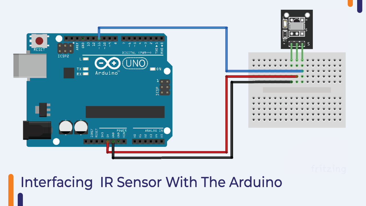
Interfacing IR Sensor With Arduino
The IR sensor has only two pins. In the following section, you can see the interfacing diagram of IR receiver with Arduino.
In the image, you can see that we have connected the Vcc pin of the sensor to the GPIO pin of the Arduino and the GND pin to the GND pin of the Arduino.
Please refer to the following image to understand the interfacing of IR sensor.
Arduino Code For IR Transmitter
You can use the following code for the IR transmitter. In the following code, we have a function that is used to generate the code that needs to be transmitted to the receiver.
Then there is another function that uses the function to generate the blinking pattern of the IR generator.
You can use the IR receiver to check the output of the sensor or you can use the camera of your phone to check the output of the sensor.
If you are using an IR receiver then you will have to use another Arduino and upload the IR receiver code to the Arduino.
And if you are using your phone’s camera then all you have to do is turn on the sensor and you have to hold your phone in front of the sensor.
When you turn on the Arduino, you will see a blinking pattern of the sensor on the screen of your phone.
You can use the following code for IR receiver to check the output.
#include <IRremote.h>
#include <IRremoteInt.h>

int RECV_PIN = 11;          //  The digital pin that the signal pin of the sensor is connected to
IRrecv receiver(RECV_PIN);  //  Create a new receiver object that would decode signals to key codes
decode_results results;     //  A varuable that would be used by receiver to put the key code into

void setup() {
  Serial.begin(9600);       //  Setup serial port to send key codes to computer
  receiver.enableIRIn();    //  Enable receiver so that it would start processing infrared signals
}

void loop() {
  if(receiver.decode(&results)) {             //  Decode the button code and put it in "results" variable
    Serial.println(results.value, HEX);       //  Print the code as a hexadecimal value
    receiver.resume();                        //  Continue listening for new signals
  }
}
IR Obstacle Sensor
In the previous part of this blog, we learned about IR transmitter and receiver.
In that, we were using two different modules to transfer the data from one place to another, but in case of IR obstacle sensor, we get both the modules on the same module.
IR sensor is an electronic device that emits light to sense an object around it.
An IR can measure the heat of an object as well as detect motion.
Normally, in the infrared spectrum, all objects radiate some form of thermal radiation.
This type of radiation is invisible to our eyes, but infrared sensors can detect these radiations.
This sensor has two modules. Those modules are as follows:
1. IR receiver
2. IR transmitter
An IR Transmitter or IR LED
An infrared transmitter is a light emitting diode (LED) that emits infrared radiation called an IR LED.
Even though an IR LED looks like a normal LED, the radiation it emits is invisible to the human eye.
IR Receiver or Photo-diode
Infrared receivers or infrared sensors detect radiation from IR transmitters. IR receivers come in the form of photodiodes and phototransistors.
The third part of the IR sensor is the gain amplifier.
The gain amplifier plays an important role when the signal quality is very low. It amplifies the week signal and generates high quality signals.
If the output of your module is not clear then you get a potentiometer on the module. You can adjust that potentiometer to amplify weak signals.
Interfacing IR Obstacle Sensor With Arduino
The interface of IR obstacle sensor with Arduino is simple. There are only three pins in this module and out of those three pins, two are power pins and one is signal pin.
The power pin you can connect to the Arduino’s power pin and the signal pin to the Arduino’s analog pin.
The following image will clear your doubts.

Arduino Code IR Obstacle Sensor
In this section, we will understand about Arduino code for IR sensor.
In the below code you can see that we have used analog read function to read the output of IR sensor.
After that, you can see that we are storing the output of the sensor in a variable. And then we have used serial.print function to print the output of sensor.
Please check the below code and if you have any doubts please mention in the comment section.
int SignalPin = 2;   // Connect the signal pin of IR module to the D2 pin of Arduino
void setup() {
  pinMode(SignalPin, INPUT); // Initialize D2 as an INput pin
  Serial.begin(9600);
}
int Object = HIGH;
void loop() {
  Object = digitalRead(obstaclePin);
  if (Object == LOW)
  {
    Serial.println("Object Not Found"); // If there is nothing in its path
    delay(200);
  }
  else
  {
    Serial.println("Obstacle Found"); //If there is obstacle
  }
  delay(100);
}
IR Flame Sensor
There are different flame sensors available in the market. What you are getting with this kit is an IR flame sensor.
IR flame sensor is used in fire systems. They detect a fire and send a signal to the controlling unit, then the controlling unit takes the necessary action to avoid fire damage. But do you know how the IR flame sensor detects fire?
The answer to the question is, IR sensors are designed to capture visible gases in the infrared spectral band.
When an explosion occurs, the light produced by the flames is reflected in the infrared spectral band and generates a flame sensor signal based on the received frequency of the light.
It was about the introduction of the flame sensor; In the next section of the blog, we will learn about interfacing flame sensors with Arduino.
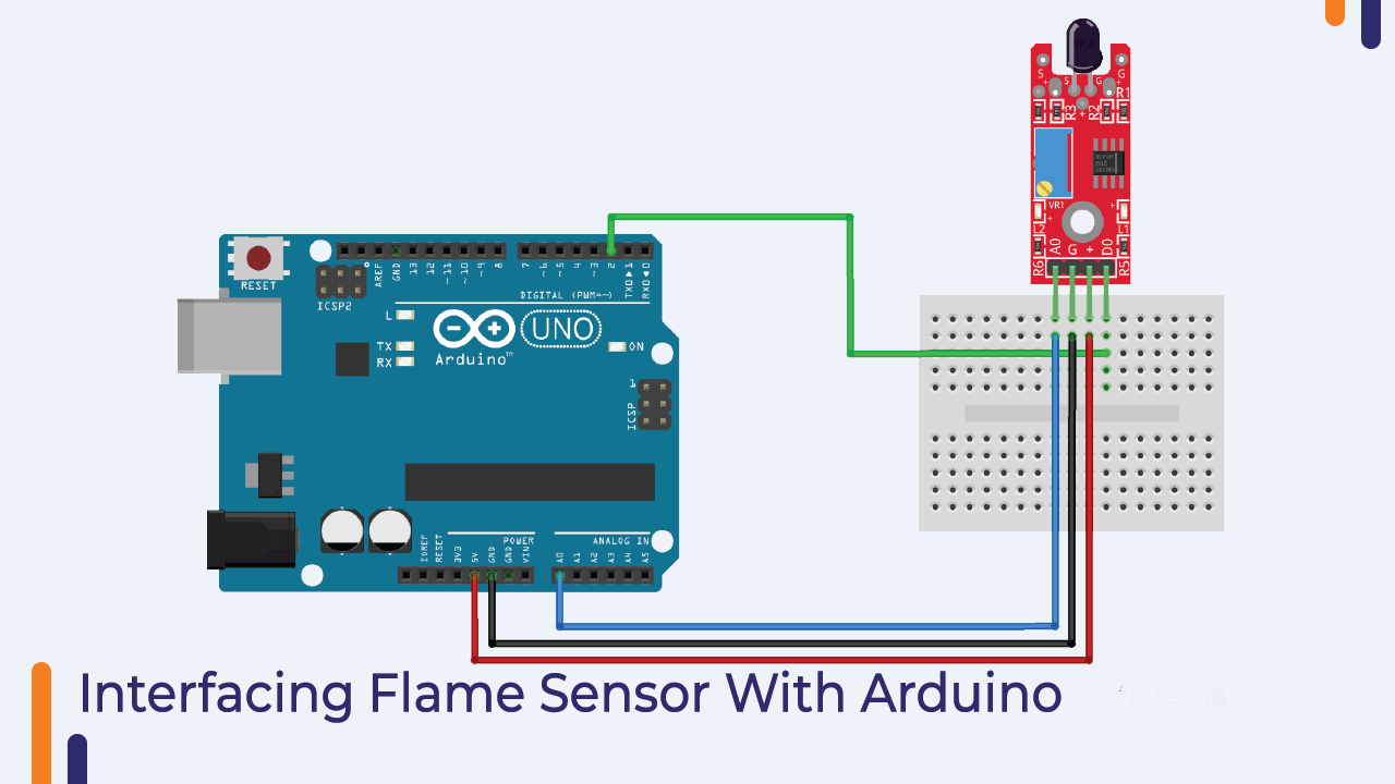
Interfacing Flame Sensor With Arduino
As we know that IR flame sensor has three pins, it is so easy to interface the IR flame sensor with Arduino.
You just need to connect the signal pin of the flame sensor to the analog pin of the Arduino and the power pins of the sensor to the power pin of the Arduino.
Please refer to the image below to understand the wiring diagram.
Arduino Code For Flame Sensor
So, as you have connected the IR flame sensor to the Arduino, we will now move to the Arduino code section of the flame sensor.
The code is very simple and does not require any explanation. In this code, we have used a variable and the function of that variable is to collect the output of IR flame sensor.
Then we are printing the output to the serial monitor.
Please use the below code.
// lowest and highest sensor readings:
const int sensorMin = 0;     // sensor minimum
const int sensorMax = 1024;  // sensor maximum

void setup() {
  // initialize serial communication @ 9600 baud:
  Serial.begin(9600);
}
void loop() {
  // read the sensor on analog 2:
	int sensorReading = analogRead(2);
  // map the sensor range (four options):
  // ex: 'long int map(long int, long int, long int, long int, long int)'
	int range = map(sensorReading, sensorMin, sensorMax, 0, 3);

  // range value:
  switch (range) {
  case 0:    // A fire closer than 1.5 feet away.
    Serial.println("** Close Fire **");
    break;
  case 1:    // A fire between 1-3 feet away.
    Serial.println("** Distant Fire **");
    break;
  case 2:    // No fire detected.
    Serial.println("No Fire");
    break;
  }
  delay(1);  // delay between reads
}
Buzzer
Buzzers are used in many instruments. It is used as an indicator in many systems such as home appliances, alarm systems, electronic bells.
Talking about the working principle of the buzzer, the buzzer converts electrical energy into sound energy.
When voltage is applied to the buzzer, the piezo crystal inside the plastic casing expands and contracts. This causes the plate to vibrate near the crystal and the sound you hear is of that vibration.
Changing the frequency to a buzzer changes the speed of the vibration and as a result you hear a variety of sounds.
So, it was about the buzzer. There are two main types of buzzers. Active buzzer and passive buzzer. In the next section of this blog, we will understand the difference between these two types.
Difference Between Active And Passive Buzzer
As I mentioned earlier, there are many types of buzzers. Active buzzer and passive buzzer.
Talking about the active buzzer, it has an inbuilt oscillating source. Active buzzers start ringing as soon as they are turned on but in case of passive buzzers they do not have an inbuilt oscillating source.
If you want a passive buzzer to produce a sound signal, you must give a different frequency to the buzzer.
Interfacing Buzzer With Arduino
No matter which buzzer you are using, it only has two pins. You can connect the vcc pin of the buzzer directly to the GPIO pin of the Arduino and the GND pin of the buzzer to the GND pin of the Arduino.
In my case, I have used an active buzzer. But you can use a passive buzzer, but remember, if you want to make a different sound from the passive buzzer, you have to give a varying frequency to the VCC pin of the buzzer.
Please check the interfacing diagram given below to understand the interfacing diagram.
As you have wired the buzzer. Now, we will move on to the Arduino code for the buzzer.

Arduino Code For Buzzer
The code for the buzzer is very simple. All you need to do is use the digitalWrite function and apply a high or low voltage to turn the buzzer on or off.
You can use the following code to turn on the buzzer.
// lowest and highest sensor readings:
const int sensorMin = 0;     // sensor minimum
const int sensorMax = 1024;  // sensor maximum

void setup() {
  // initialize serial communication @ 9600 baud:
  Serial.begin(9600);
}
void loop() {
  // read the sensor on analog 2:
	int sensorReading = analogRead(2);
  // map the sensor range (four options):
  // ex: 'long int map(long int, long int, long int, long int, long int)'
	int range = map(sensorReading, sensorMin, sensorMax, 0, 3);

  // range value:
  switch (range) {
  case 0:    // A fire closer than 1.5 feet away.
    Serial.println("** Close Fire **");
    break;
  case 1:    // A fire between 1-3 feet away.
    Serial.println("** Distant Fire **");
    break;
  case 2:    // No fire detected.
    Serial.println("No Fire");
    break;
  }
  delay(1);  // delay between reads
}
Vibration Sensor
Vibration sensors are used in many devices such as mechanical machines.
It is used to measure the frequency of vibrations generated by machines and those measured frequencies are then converted into voltage signals.
The vibration sensor we get with this kit has an onboard gain amplifier.
That amplifier is used to adjust the gain of the module.
If the signals generated by the vibration sensor are not accurate, you can adjust the trimmer next to the gain amplifier.
The vibration sensor is easy to use.
In the next section, we’ll talk about interfacing the vibration sensor with the Arduino.
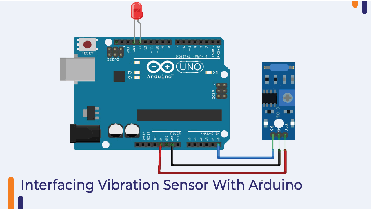
Interfacing Vibration Sensor With Arduino
It is very easy to interface the vibration sensor with Arduino. It has three pins, two for powering the module and one for output.
We need to connect the power pin of the vibration sensor to the Arduino and the signal pin to any GPIO pin of the Arduino.
You can refer to the following image to understand the wiring diagram.
Arduino Code For Vibration Sensor
In the following code, we have used analog read method to read the output of the sensor and we are printing the output on the serial monitor.
You can use the following code to read the output of the sensor.
// lowest and highest sensor readings:
const int sensorMin = 0;     // sensor minimum
const int sensorMax = 1024;  // sensor maximum

void setup() {
  // initialize serial communication @ 9600 baud:
  Serial.begin(9600);
}
void loop() {
  // read the sensor on analog 2:
	int sensorReading = analogRead(2);
  // map the sensor range (four options):
  // ex: 'long int map(long int, long int, long int, long int, long int)'
	int range = map(sensorReading, sensorMin, sensorMax, 0, 3);

  // range value:
  switch (range) {
  case 0:    // A fire closer than 1.5 feet away.
    Serial.println("** Close Fire **");
    break;
  case 1:    // A fire between 1-3 feet away.
    Serial.println("** Distant Fire **");
    break;
  case 2:    // No fire detected.
    Serial.println("No Fire");
    break;
  }
  delay(1);  // delay between reads
}
Single Channel Relay Module
Relay modules can be found on many electronic devices. It is an electromagnetic switch used to switch devices with high voltage requirements using low-level input signals.
In this section, we are going to understand the interfacing of relay with Arduino and understand some basics of relay module.
There are six pins in a relay module, three of those six pins are inputs and two are outputs. I have explained the function of those pins below please have a look.
Normally Open
This is the output pin of the relay module. This pin remains open till the relay module coil is energized.
NC Normally Closed
This is also an output pin. This pin remains connected to the common terminal until the relay module is activated.
Common Pin
This is an input pin. When the relay module is powered on the normally open pin and the common terminal will connect to each other and when the relay module power is turned off the common terminal will connect to the normally closed terminal.
VCC Pin And GND Pin
These two pins are the power pins and are connected to the internal coil of the relay.
The relay module we are getting with this kit has an operating voltage of 5V for its coil.
So, we can directly connect the 5V supply to this pin.
Signal Pin
This pin is connected to the base terminal of the SMD transistor which is present on the relay module. When we give 5V to this pin, this pin will power on the relay coil.
So, it was about the introduction of the relay module. In the next part of this blog, we will understand the interfacing of the relay module.
Interfacing Relay Module With Arduino
In this section, we will learn about the interfacing of the relay module with Arduino.
As discussed earlier, there are six pins in the relay module and three of those five pins are input pins.
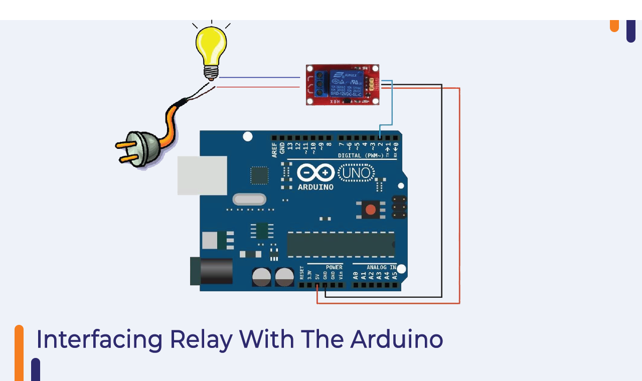
In the image above you can see those three pins.
You can see GND, VCC and signal pins over there.
You can connect the relay module’s GND and VCC pins to the Arduino’s VCC and GND pins and the relay module’s signal pin to any GPIO pin of the Arduino.
This was about one end of the relay module now we will understand the connections on the other side.
In the image above you can see the COM, NC and NO pins. These are connected to the load.
I hope you are clear with the connection diagram now. If you have any doubts please let us know in the comment section.
Arduino Code to Control Relay Module
In this section, we will understand the Arduino code which we will be using in the relay module.
So, the relay is connected to the Arduino and the Arduino is providing power to the relay module, so we have to use the digitalWrite function.
I have added below 200 seconds delay between execution of two tasks. The reason for adding a delay between the two functions is that if there is no delay between the relay on and off event then we will not be able to understand the difference between these two events.
So, to understand the difference between these two functions, I have used the delay function.
If you have any doubts then mention your issues in the comment section below.
int relay = 8;
volatile byte relayState = LOW;

// PIR Motion Sensor is connected to D2.
int PIRInterrupt = 2;

// Timer Variables
long lastDebounceTime = 0;
long debounceDelay = 10000;

void setup() {
  // Pin for relay module set as output
  pinMode(relay, OUTPUT);
  digitalWrite(relay, HIGH);
  // PIR motion sensor set as an input
  pinMode(PIRInterrupt, INPUT);
  // Triggers detectMotion function on rising mode to turn the relay on, if the condition is met
  attachInterrupt(digitalPinToInterrupt(PIRInterrupt), detectMotion, RISING);
  // Serial communication for debugging purposes
  Serial.begin(9600);
}

void loop() {
  // If 10 seconds have passed, the relay is turned off
  if((millis() - lastDebounceTime) > debounceDelay && relayState == HIGH){
    digitalWrite(relay, HIGH);
    relayState = LOW;
    Serial.println("OFF");
  }
  delay(50);
}

void detectMotion() {
  Serial.println("Motion");
  if(relayState == LOW){
    digitalWrite(relay, LOW);
  }
  relayState = HIGH;
  Serial.println("ON");
  lastDebounceTime = millis();
}
Reed Switch
Reed switch is one of the contactless switches. These switches are used in many applications like cars, washing machines and burglar systems are one of the most popular applications.
In this section of this blog, we will understand the working of the reed switch.
We are getting two types of reed switches with the kit. In the next part of this blog we will understand the basics of reed switch.
There are two ferromagnetic contacts inside the reed switch. These contacts are placed two microns apart from each other.
When a magnet is placed near this switch, the ferromagnet blades will be attracted to each other.
This way, the connection will be done and we will get either a high-level output or a low-level output depending on the type of input given to the reed switch.
So, this was the basic information about the reed switch. If you have any doubts please let us know in the comment section.
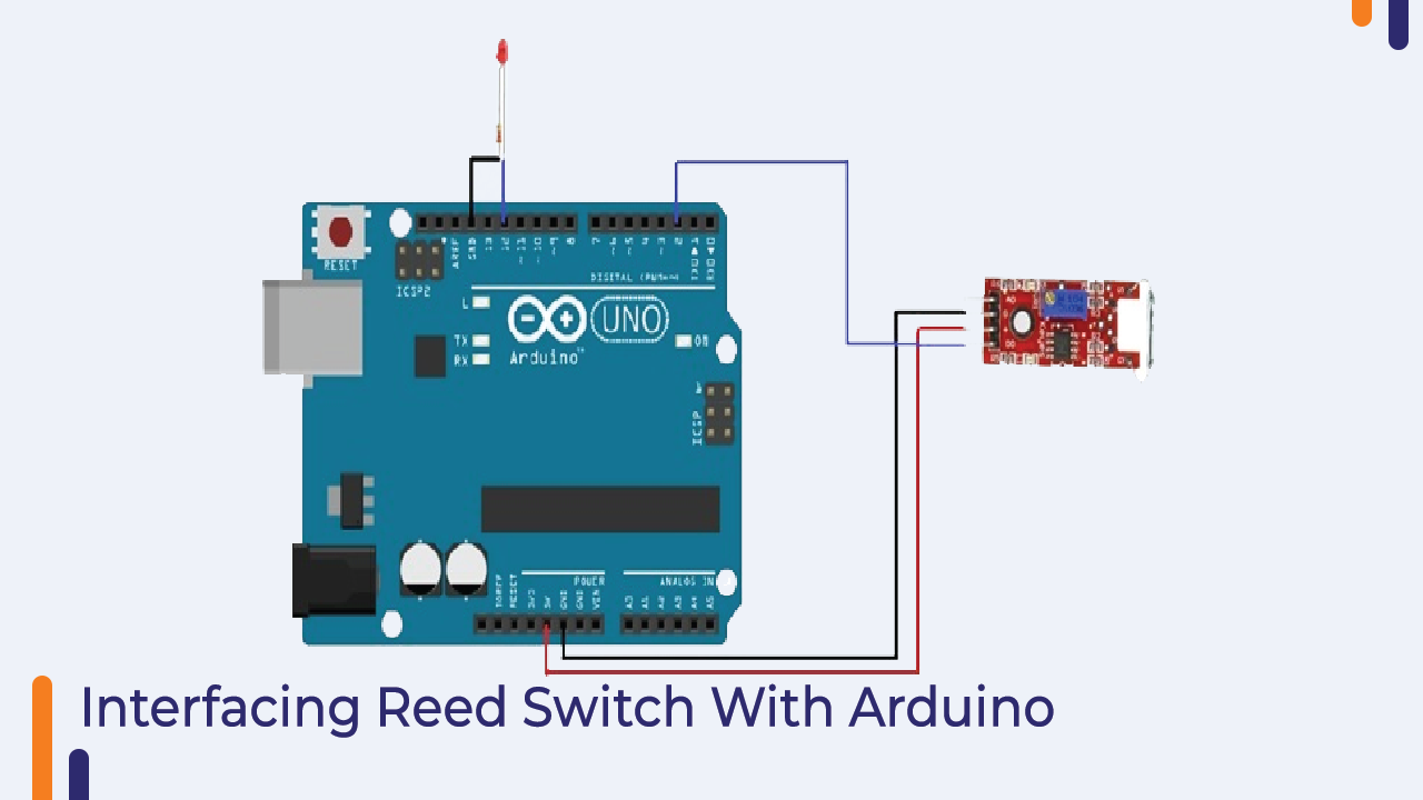
Interfacing Reed Switch With Arduino
Reed switches have two pins. You can connect one end of the reed switch to the 5v pin of the Arduino and the other end of the reed switch to any GPIO pin of the Arduino.
The following image shows the interfacing diagram of the reed switch with the Arduino.
Arduino Code For Reed Switch
In the following Arduino code, we have used the digitalRead function to read the output of the sensor.
You can upload the code to your Arduino and see the output of the code on the serial monitor.
int LED = 12;
int reed_switch = 2;
int reed_status;

void setup()
{
  pinMode(LED, OUTPUT);
  pinMode(reed_switch, INPUT);
}

void loop()
{
  reed_status = digitalRead(reed_switch);
  if (reed_status == 1)
    digitalWrite(LED, LOW);
  else
    digitalWrite(LED, HIGH);
  delay(1000);
}
Analog and Digital Temperature Sensor
With this kit we are getting two temperature sensors. We can use both these sensors in our IoT projects.
Analog Temperature Sensor
Digital temperature sensor
The analog temperature sensor has a thermocouple sensor, the output of the thermocouple sensor changes according to the change in temperature.
Talking about digital temperature sensor, this sensor generates either high voltage or low voltage.
This was the simple introduction to the temperature sensor; In the next part of this blog, we will discuss how to interface analog and digital sensors with Arduino.
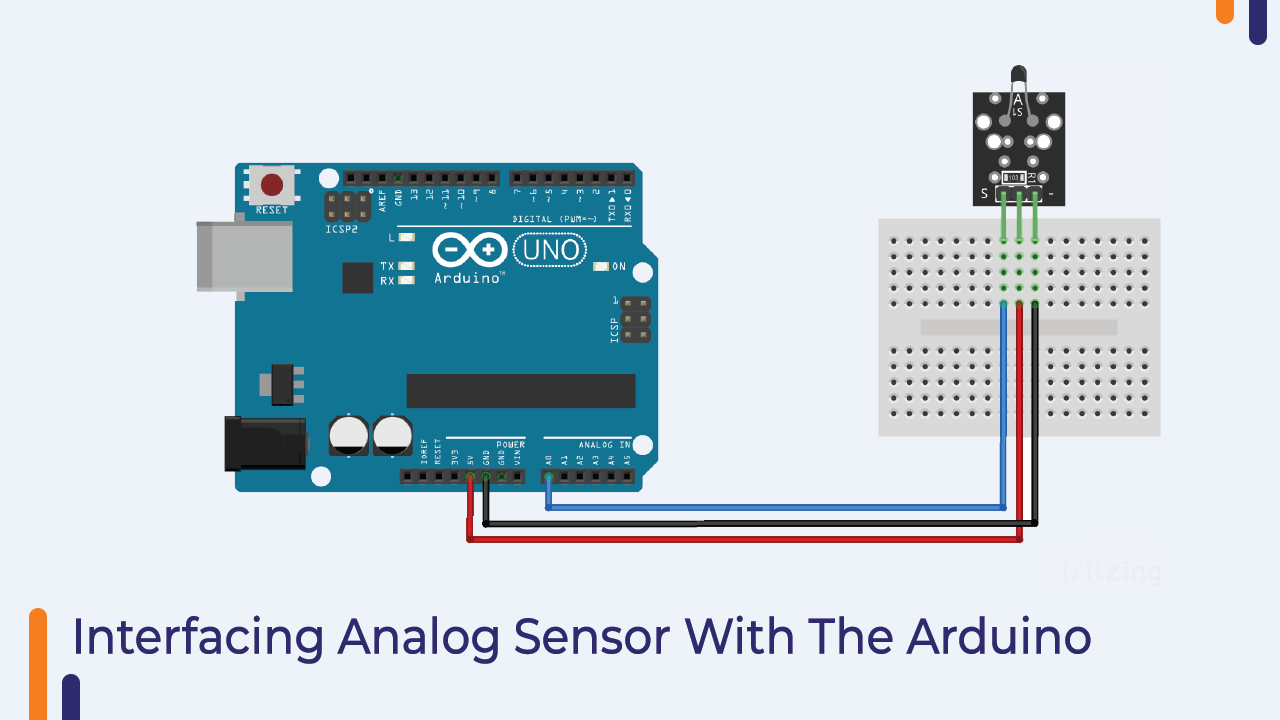
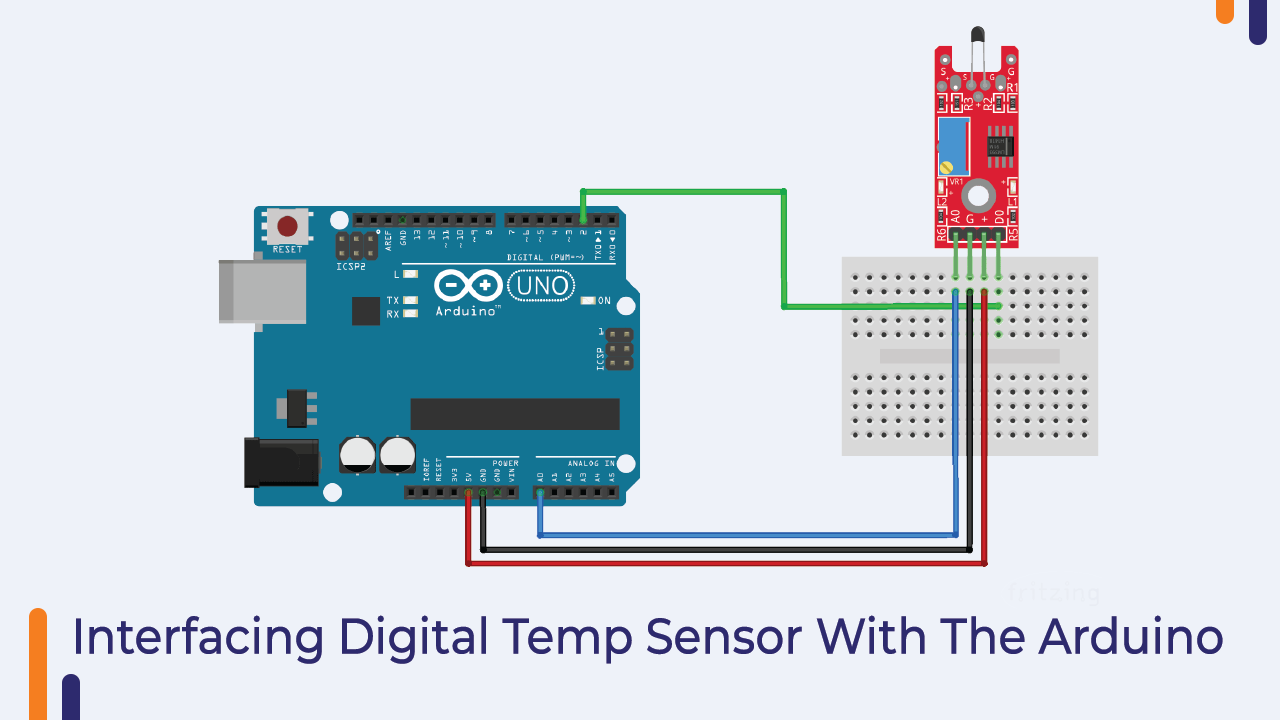
Interfacing Temperature Sensor With Arduino
Both analog and digital temperature sensors have three pins. Two of those three pins are the power pin and one is the signal pin.
We can connect the signal pins of those sensors to any GPIO pin of Arduino.
Please check the following images to understand the connection diagram.
Interfacing Diagram For Analog Temperature Sensor
Connection Diagram For Digital Temperature Sensor
Arduino Code For Temperature Sensor
We have learned about interfacing sensors with Arduino. Now, as we know how analog and digital sensors work, we can design our logic to read the output of the sensor.
So far, we have understood that the analog read function is used to read the analog values and the digital read function is used to read the digital output of the sensor.
In the temperature sensor code, we are using both these functions to get the output of the sensor.
I have shared two code snippets below. One code snippet is for the analog temperature sensors and the other is for the digital temperature sensors.
Arduino Code For Analog Sensor
int ThermistorPin = A0;
int Vo;
float R1 = 10000; // value of R1 on board
float logR2, R2, T;
float c1 = 0.001129148, c2 = 0.000234125, c3 = 0.0000000876741; //steinhart-hart coeficients for thermistor

void setup() {
  Serial.begin(9600);
}

void loop() {
  Vo = analogRead(ThermistorPin);
  R2 = R1 * (1023.0 / (float)Vo - 1.0); //calculate resistance on thermistor
  logR2 = log(R2);
  T = (1.0 / (c1 + c2*logR2 + c3*logR2*logR2*logR2)); // temperature in Kelvin
  T = T - 273.15; //convert Kelvin to Celcius
 // T = (T * 9.0)/ 5.0 + 32.0; //convert Celcius to Farenheit

  Serial.print("Temperature: ");
  Serial.print(T);
  Serial.println(" C");

  delay(500);
}
Arduino Code For Digital Sensor
int led = 13; // define the LED pin
int digitalPin = 2; // KY-028 digital interface
int digitalVal; // digital readings

void setup()
{
  pinMode(led, OUTPUT);
  pinMode(digitalPin, INPUT);
  Serial.begin(9600);
}

void loop()
{
  // Read the digital interface
  digitalVal = digitalRead(digitalPin);
  if(digitalVal == HIGH) // if temperature threshold reached
  {
    digitalWrite(led, HIGH); // turn ON Arduino's LED
  }
  else
  {
    digitalWrite(led, LOW); // turn OFF Arduino's LED
  }


  delay(100);
}
Please upload the code to your Arduino and see the sensor’s output on the serial monitor.
DHT11 Temperature And Humidity Sensor Module
If you are working on an IoT project then this sensor will help you to collect the data of the surrounding environment.
This sensor has inbuilt capacitive temperature sensor and thermometer.
The DHT11 sensor is designed in such a way that it will retain moisture.
When the substrate of the sensor is covered with water vapor the substrate starts to generate ions.
The substrate continues to generate ions depending on the amount of the water vapour.
An increase in ions will decrease the resistance between the two electrodes.
Now as the resistance between the two electrodes is decreasing, we will see a change in the voltage reading.
And we can calculate the humidity based on the variations found in the output of the sensor.
Talking about the temperature sensor, the NTC type thermistor has been given in the DHT11 sensor. This thermistor is nothing but a temperature sensor.
The output value of the thermistor changes according to the change in the surrounding temperature. So by calculating the change in the output voltage of the sensor we can find out the temperature reading.
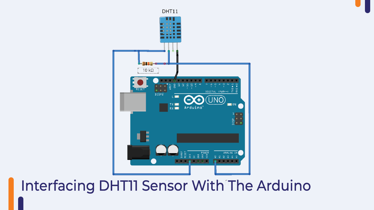
Interfacing DHT11 Sensor With Arduino
In the following section, I have shown the interfacing diagram of DHT11 sensor with Arduino.
The DHT11 sensor has three pins. You can connect those three pins to Arduino as shown in the picture below.
Arduino Code DHT11 Interfacing With Arduino
In this code, we are using the DHT.h library. This library will take care of all the timing requirements and return only the required results.
Please use the following line code to work with the DHT11 sensor. If you have any doubts please let us know we will be happy to assist you.
#include "DHT.h"

#define DHTPIN A0     // Digital pin connected to the DHT sensor

#define DHTTYPE DHT11   // DHT 11
//#define DHTTYPE DHT22   // DHT 22  (AM2302), AM2321
//#define DHTTYPE DHT21   // DHT 21 (AM2301)

// Connect pin 1 (on the left) of the sensor to +5V
// NOTE: If using a board with 3.3V logic like an Arduino Due connect pin 1
// to 3.3V instead of 5V!
// Connect pin 2 of the sensor to whatever your DHTPIN is
// Connect pin 4 (on the right) of the sensor to GROUND
// Connect a 10K resistor from pin 2 (data) to pin 1 (power) of the sensor

// Initialize DHT sensor.
// Note that older versions of this library took an optional third parameter to
// tweak the timings for faster processors.  This parameter is no longer needed
// as the current DHT reading algorithm adjusts itself to work on faster procs.

DHT dht(DHTPIN, DHTTYPE);

void setup() {
  Serial.begin(9600);
  Serial.println(F("DHTxx test!"));

  dht.begin();
}

void loop() {
  // Wait a few seconds between measurements.
  delay(2000);

  // Reading temperature or humidity takes about 250 milliseconds!
  // Sensor readings may also be up to 2 seconds 'old' (its a very slow sensor)
  float h = dht.readHumidity();
  // Read temperature as Celsius (the default)
  float t = dht.readTemperature();
  // Read temperature as Fahrenheit (isFahrenheit = true)
  float f = dht.readTemperature(true);

  // Check if any reads failed and exit early (to try again).
  if (isnan(h) || isnan(t) || isnan(f)) {
    Serial.println(F("Failed to read from DHT sensor!"));
    return;
  }

  // Compute heat index in Fahrenheit (the default)
  float hif = dht.computeHeatIndex(f, h);
  // Compute heat index in Celsius (isFahreheit = false)
  float hic = dht.computeHeatIndex(t, h, false);

  Serial.print(F(" Humidity: "));
  Serial.print(h);
  Serial.print(F("%  Temperature: "));
  Serial.print(t);
  Serial.print(F("C "));
  Serial.print(f);
  Serial.print(F("F  Heat index: "));
  Serial.print(hic);
  Serial.print(F("C "));
  Serial.print(hif);
  Serial.println(F("F"));
}
Switch Module
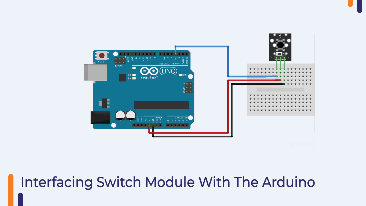
We are getting the switch module with this kit. You can use this module if you are working on a project that requires switches.
This switch module has three pins. Two of those three pins are the power pin and one pin is the signal pin.
In the following image I have shown the interfacing diagram of the switch please have a look and if any doubt please let us know in the comment section.
Arduino Code For Switch Module
When we press the switch the switch module will generate a high-level signal.
So, if we want to read the output of the sensor then we have to use the digitalRead function.
In the following code, you can see that we have used the digitalRead function and then printing it on a serial monitor.
Please use the below code to test the switch module.
// constants won't change. They're used here to
// set pin numbers:
const int buttonPin = 3;     // the number of the pushbutton pin
const int ledPin =  13;      // the number of the LED pin

// variables will change:
int buttonState = 0;         // variable for reading the pushbutton status

void setup() {
  // initialize the LED pin as an output:
  pinMode(ledPin, OUTPUT);
  // initialize the pushbutton pin as an input:
  pinMode(buttonPin, INPUT);
}

void loop() {
  // read the state of the pushbutton value:
  buttonState = digitalRead(buttonPin);

  // check if the pushbutton is pressed.
  // if it is, the buttonState is HIGH:
  if (buttonState == HIGH) {
    // turn LED on:
    digitalWrite(ledPin, HIGH);
  } else {
    // turn LED off:
    digitalWrite(ledPin, LOW);
  }
}
Mercury Switch Module
We are getting a Mercury Switch Module with this product. The mercury switch is used to measure the inclination.
Talking about the construction of this switch, it has two electrical contacts which are enclosed in a cylindrical shape made of glass material.
When the switch is tilted the mercury inside the glass envelope attaches to the terminals of the switch and acts as a medium for the flow of current between the two terminals of the switch.
Usually in normal switches, when we turn them on, a little arcing current can be observed, which generates EMI (Electromagnetic Interference) in the electronic circuit.
But in case of mercury switch, the arc gets absorbed by the mercury.
So, the use of mercury switch module minimizes the effects of EMI (electromagnetic interference) and that is why it is the most suitable switch module in applications where EMI is the most concern.
Interfacing Mercury-Switch Module With Arduino
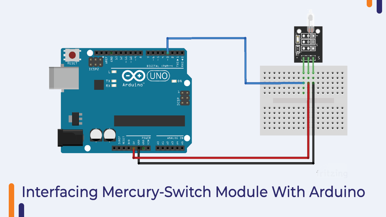
Talking about the connection diagram of the mercury-switch module, the mercury-switch module has three pins which we are getting with the kit there are only three pins. VCC GND & Signal.
VCC and GND pins are power pins of sensor and signal pins which we can connect to any GPIO of Arduino.
Please refer to the following picture to understand the working of Mercury-Switch module.
Arduino Code For Mercury Switch Module
As discussed earlier, when we tilt the sensor, the sensor will generate a high-level signal and if we are using an Arduino then to read the output of the sensor, we can use the digitalRead function Huh.
In the following code, you can see that we are using digitalRead function and storing the output of the sensor in a variable.
Please use the following code and if any doubt please let us know.
int led_pin = 13; // Define the LED interface
int switch_pin = 3; // Definition of mercury tilt switch sensor interface
int val; // Defines a numeric variable

void setup()
{
	pinMode(led_pin, OUTPUT);
	pinMode(switch_pin, INPUT);
}

void loop()
{
	val = digitalRead(switch_pin); // check mercury switch state
	if(val == HIGH)
	{
		digitalWrite(led_pin, HIGH);
	}
	else
	{
		digitalWrite(led_pin, LOW);
	}
}
So, it was about the Mercury-Switch module, in the next part of this blog we will learn about the Magic Cup module.
Magic Cup Module
The working principle of the Magic Cup module is similar to that of the Mercury Switch module. The only difference is that in this module you get two LEDs.
Those LEDs are used for indication purposes. When you tilt the sensor, the brightness of one LED will start increasing and the brightness of the other LED will start decreasing.
So, this was the basic introduction to the Magic Cup module with Arduino.
In the next part of this blog, we will understand the interfacing of the Magic Cup module.
Interfacing Of Magic Cup Module
The Magic Cup module has four pins. You get two things on board; There is an LED module and a mercury switch.
The following interfacing image will clear your doubts.
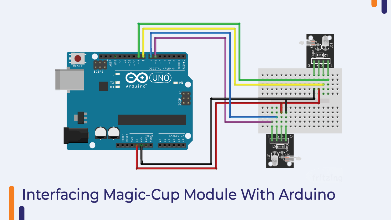
I have explained the control logic in the following section please have a look and if any doubt please mention in the comment section.
Arduino Code For Magic-Cup Module
As we have connected the Magic Cup module to the Arduino, now we can write our code to get the output from the module.
As discussed earlier, we will receive the sensor output at the signal pin. In the following code, we have used a variable to store the output of the sensor.
In the code below, we are continuously checking the output of the sensor and once the state of the variable changes, we are tuning the LED.
Please take a look at the following code and if you have any doubts please let us know.
int LedPinA = 6;
int LedPinB = 9;
int ButtonPinA = 7;
int ButtonPinB = 8;
int buttonStateA = 0;
int buttonStateB = 0;
int brightness = 0;
void setup ()
{
pinMode (LedPinA, OUTPUT);
pinMode (LedPinB, OUTPUT);
pinMode (ButtonPinA, INPUT);
pinMode (ButtonPinB, INPUT);
}
void loop ()
{
buttonStateA = digitalRead (ButtonPinA);
if (buttonStateA == HIGH&&brightness!= 255)
{
brightness ++ ;
}
buttonStateB = digitalRead (ButtonPinB);
if (buttonStateB == HIGH&&brightness!= 0)
{
brightness -- ;
}
analogWrite (LedPinA, brightness); // A few Guan Yuan (ii) ?
analogWrite (LedPinB, 255 - brightness);// B Yuan (ii) a few Bang ?
delay (5); // number can be changed. larger number = longer light swap.
}
Microphone Sound Sensor
We are getting Two Types of Sound Sensors in this kit.
The working of these sound sensors is the same. In the next section, we will understand the working of a sound sensor.
The sound sensor is designed to convert an analog signal into a digital signal. They convert any sound signals into digital signals.
We can see these sensors everywhere. These sensors act as the ears of the electronic circuit. But do you know how they work?
These sensors contain a diaphragm, a type of piezoelectric transducer that converts sound frequency into electrical signals.
When the sound frequency hits this sensor, the diaphragm surface vibrates and then depending on the intensity of the sound signals the diaphragm generates voltage.
This is how the sound sensor converts the sound frequency into electrical signals.
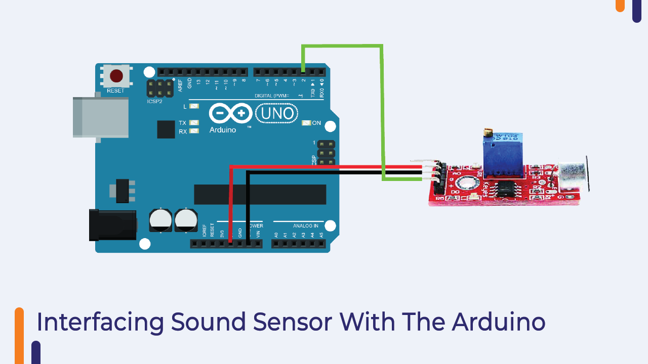
Interfacing Sound Sensor With Arduino
The sound sensor has three pins and we get the sensor’s output at the signal pin of the module.
We have connected the signal pin of the module to the number seven GPIO pin of the Arduino.
I have shared the images of both the modules below please have a look.
Arduino Code For Microphone Sensor
We are getting the output of the sound sensor on the GPIO pin of Arduino but the format of the signal is analog, so we have used analog read function to read the output of the sensor.
In the below code we are reading the output and printing the output to serial monitor.
To check the output of the module you have to open the serial monitor.
int Led = 13 ;// define LED Interface
int buttonpin = 2; // define D0 Sensor Interface
int val = 0;// define numeric variables val

void setup ()
{
  pinMode (Led, OUTPUT) ;// define LED as output interface
  pinMode (buttonpin, INPUT) ;// output interface D0 is defined sensor
}

void loop ()
{
  val = digitalRead(buttonpin);// digital interface will be assigned a value of pin 3 to read val
  if (val == HIGH) // When the sound detection module detects a signal, LED flashes
  {
    digitalWrite (Led, HIGH);
  }
  else
  {
    digitalWrite (Led, LOW);
  }
}
Broken LED Module/ Photocoupler
We are finding this very useful module with this kit. This type of switch is mostly used in 3D printing machines and applications where the problem of electronic interference is of greatest concern.
These switches consist of an optical emitter and an optical receiver.
Talking about the optical emitter, it is nothing but the LED which emits light continuously and the optical receiver which is placed right in front of the optical emitter keeps on receiving the light which is being transmitted by the optical emitter.
The optical receiver is nothing but a photodiode. When the light rays fall on the photodiode, the barrier gap between the pn junction of the photodiode starts decreasing and at one point the barrier gap becomes zero and the photodiode acts as a switch.
Thus, as long as light is not falling on the photodiode the photodiode will continue to act as a closed switch and when the light source is gone it acts as an open switch.
Please see the following image for better understanding.

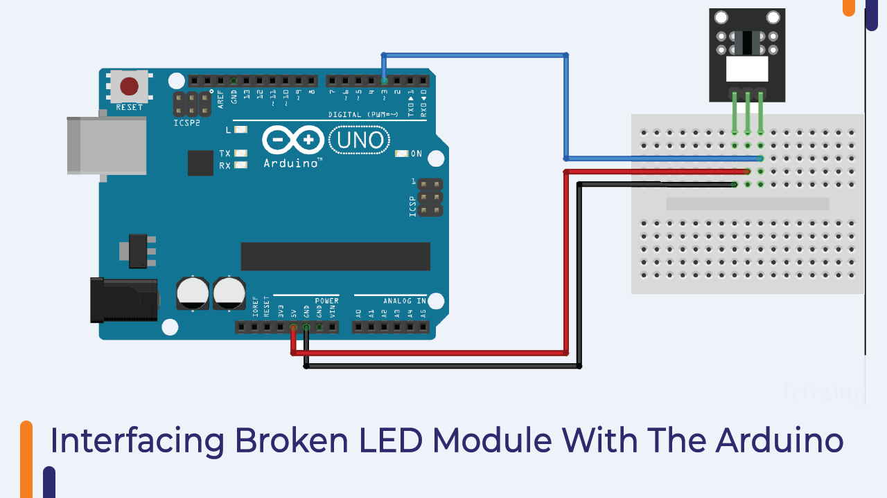
Interfacing of The Broken LED Module With The Arduino
In the following image I have shown the interfacing of LED with Arduino. Broken LED module has three pins. Of those three pins, S is the signal pin. I have connected that pin to pin number seven of Arduino.
Please see the following image to understand the connection diagram.
Arduino Code For Broken LED Module
In this section we are discussing about the codes for broken light LED. As we have discussed earlier the broken light LED module generates either high voltage or low voltage.
So, to read the output of the sensor we have to use the digitalRead function. In the below code we have used digitalRead function and we are printing the output of sensor on serial monitor.
You can See the output of the sensor by opening the serial monitor.
Initially when there will be no obstacle between optical emitter and optical receiver, we will see ‘switch on signal’ on the screen but when we put an obstacle between optical emitter and optical receiver we will see ‘switch is off’ screen.
int Led = 13; // define LED pin
int buttonpin = 3; // define photo interrupter signal pin
int val; //define a numeric variable

void setup()
{
	pinMode(Led, OUTPUT); // LED pin as output
	pinMode(buttonpin, INPUT); //photo interrupter pin as input
}

void loop()
{
	val=digitalRead(buttonpin); //read the value of the sensor
	if(val == HIGH) // turn on LED when sensor is blocked
	{
		digitalWrite(Led,HIGH);
	}
	else
	{
		digitalWrite(Led,LOW);
	}
}
Rotary Encode/ Potentiometer
Nowadays we can see rotary encoders everywhere. These modules can be seen being used from our car audio system to plane control panel.
These potentiometers are used to generate variations in the applied voltage. The output voltage of these potentiometers varies when we rotate them.
Potentiometers are nothing but variable resistors. The working principle of potentiometer is similar to the working principle of rheostat.
Now you must be wondering what is a rheostat? If we explain these two terms in a simple way, potentiometers are designed to change DC voltage whereas rheostats are designed to change AC voltage.
Talking about the working of Rotary Encoder (Potentiometer) there is a variable contact inside it, when we turn the knob then the position of that variable contact changes and so does the resistance and we get different voltage on its output pin.
This is how the potentiometer works. If you want to know more about potentiometer you can refer to the e-book. I have explained the rotary encoder in a detailed manner over there.
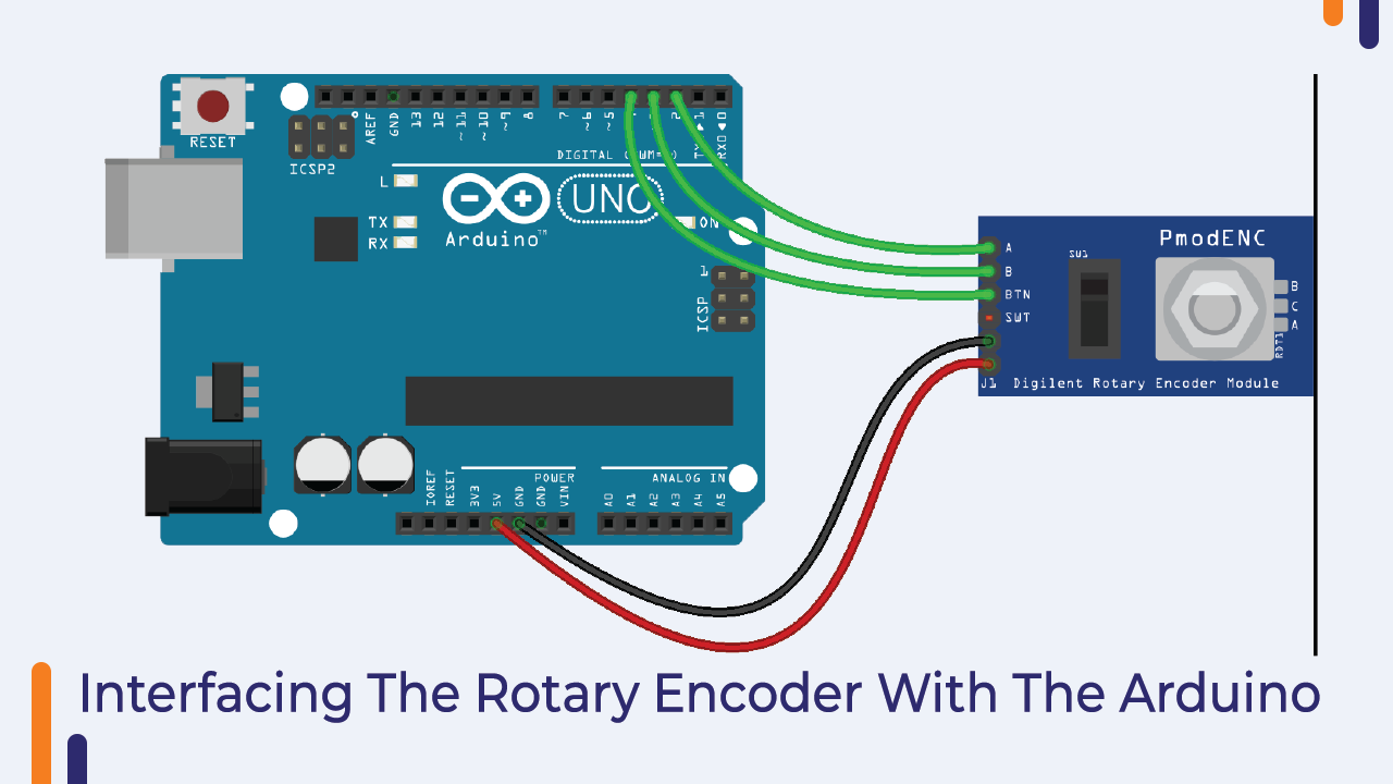
Interfacing Rotary Encoder With Arduino
In this section, we are understanding the interfacing of Rotary Encoder with Arduino.
There are three pins in a rotary encoder. Output, VCC and GND.
Output Pin of Rotary Encoder We can connect any analog pin of Arduino.
And the power pin to the power pin of the arduino.
Please refer to the following image to understand the interfacing diagram of the sensor with Arduino.
Arduino Code For Rotary Encoder
The output of the sensor is connected to the analog pin and the output type of the sensor is analog so we have to use the analog read function to read the output of the sensor.
In the following code, we have used the analog read function to read the output of the sensor.
Please refer the following code to work with rotary encoder.
Arduino Code:
#define CLK 2
#define DT 3
#define SW 4

int counter = 0;
int currentStateCLK;
int lastStateCLK;
String currentDir ="";
unsigned long lastButtonPress = 0;

void setup() {

	// Set encoder pins as inputs
	pinMode(CLK,INPUT);
	pinMode(DT,INPUT);
	pinMode(SW, INPUT_PULLUP);

	// Setup Serial Monitor
	Serial.begin(9600);

	// Read the initial state of CLK
	lastStateCLK = digitalRead(CLK);
}

void loop() {

	// Read the current state of CLK
	currentStateCLK = digitalRead(CLK);

	// If last and current state of CLK are different, then pulse occurred
	// React to only 1 state change to avoid double count
	if (currentStateCLK != lastStateCLK  && currentStateCLK == 1){

		// If the DT state is different than the CLK state then
		// the encoder is rotating CCW so decrement
		if (digitalRead(DT) != currentStateCLK) {
			counter --;
			currentDir ="CCW";
		} else {
			// Encoder is rotating CW so increment
			counter ++;
			currentDir ="CW";
		}

		Serial.print("Direction: ");
		Serial.print(currentDir);
		Serial.print(" | Counter: ");
		Serial.println(counter);
	}

	// Remember last CLK state
	lastStateCLK = currentStateCLK;

	// Read the button state
	int btnState = digitalRead(SW);

	//If we detect LOW signal, button is pressed
	if (btnState == LOW) {
		//if 50ms have passed since last LOW pulse, it means that the
		//button has been pressed, released and pressed again
		if (millis() - lastButtonPress > 50) {
			Serial.println("Button pressed!");
		}

		// Remember last button press event
		lastButtonPress = millis();
	}

	// Put in a slight delay to help debounce the reading
	delay(1);
}
Final Words– Orange 37 in1 Sensor Kit
In the next part of this blog, we will learn to do some projects using the components of this kit.
And if you have any doubt regarding any part of this blog then please let me know in the comment section.