
Introduction To Orange Arduino Intermediate Kit
Hello geeks, welcome! When I was learning Arduino, there was no one to teach me. I learned the arduino myself but it took me so much time and money.
Since there was no instructor to instruct me, I wasn’t sure where to start and what components to buy, so I bought several random components and never managed to learn them.
And the reason was the Steps. In learning new things, the steps we take plays an important role.
At that point, I learned that, we can’t start learning new things by choosing any random topic out of those new things. There must be an order of the steps to learn a new thing.
After realizing this I narrowed down my roadmap of learning Arduino by setting out one simple step.
I did some research before narrowing down those steps. And those steps really helped me to learn Arduino well!!
In this kit blog, I have shared all those steps.
And I am sure that no newcomer will feel any difficulty in learning the arduino.
Moreover, the information we have shared in this Orange Intermediate Kit blog is so detailed and easy to understand and I believe that you will not face any kind of problem in learning this Orange Intermediate Kit and arduino.
Component List
| Sr No. | Components Name | Quantity |
|---|---|---|
| 1. | Arduino Ch340G Uno | 1 |
| 2. | Arduino Uno USB Cable | 1 |
| 3. | LCD1602 IIC/I2C Blue Backlight | 1 |
| 4. | Servo SG90 9g 180 Degree | 1 |
| 5. | 65pcs Flexible Breadboard Jumper Wires | 1 |
| 6. | 830 Ponits Soldless Breadboard | 1 |
| 7. | 5V 4-Phase Stepper Step Motor | 1 |
| 8. | ULN2003 Driver Board Stepper Motor Green | 2 |
| 9. | DS1302 RTC Real Time Clock Module (No Battery) | 1 |
| 10. | IR Remote Control (No Battery) | 1 |
| 11. | MFRC-522 RC522 RFID + S50 Card + Keychain | 5 |
| 12. | 1.64FT USB 2.0 A-B Male Printer Cable 0.5m | 1 |
| 13. | PS2 Game JoyStick Module | 1 |
| 14. | 1 Channel Relay 5V | 15 |
| 15. | Sound Sensor Module | 1 |
| 16. | DIP 3 Color LED Module | 1 |
| 17. | DHT11 Temperature and Humidity Sensor Module | 1 |
| 18. | Rain Water Level Detection Sensor Module | 1 |
| 19. | 0.56 inch Red 1 Digit 7 Segment LED Display 10pin | 1 |
| 20. | 0.56 inch Red 4 Digit 7 Segment LED Display 12pin | 1 |
| 21. | 8×8 Red 64 LED Dot Matrix Displays 3mm CA | 1 |
| 22. | 12x12x7.3mm Tactile Push Button Switch Square | 5 |
| 23. | Round Cap for Square Tachile Switch | 5 |
| 24. | 10K Potentiometer 15mm Shaft | 1 |
| 25. | 9V Battery Connector with DC | 1 |
| 26. | Two Layer Storage Box, size 23.416.86.2cm | 1 |
| 27. | 10 Pin Connecting Cables | 1 |
| 28. | 28mm Leg LED 5MM Red (1pcs) | 1 |
| 29. | 28mm Leg LED 5MM Green (1pcs) | 1 |
| 30. | 28mm Leg LED 5MM Yellow (1pcs) | 1 |
| 31. | 5mm 5528 LDR Light Dependent Resistor | 1 |
| 32. | 5V Active Buzzer | 1 |
| 33 | 5V passive Buzzer | 1 |
| 34 | SW-520D Vibration Sensor Metal Ball Tilt Switch | 1 |
| 35 | Resistor 1K 1/4W 1%(1pcs) | 10 |
| 36 | Resistor 10K 1/4W 1%(1pcs) | 10 |
| 37 | Resistor 220R 1/4W 1%(1pcs) | 10 |
| 38 | LM35DZ ORI. | 1 |
| 39 | 74HC595N | 1 |
| 40 | 4×4 Matrix 16 Keypad Keyboard Module 16 Button Mcu | 1 |
| 41 | 5mm 940nm Infrared Receiver LED IR Diode LED (Flame Sensor) | 1 |
| 42 | 1838B IR Receiving Head Remote Control Receiver | 1 |
This Orange Arduino Intermediate Kit is available in three variants. You can choose your kit based on your requirement.
1 .Orange Intermediate Kit For Arduino Uno
2. Orange Intermediat Kit For Arduino Mega
3. Orange Intermediat Kit For Arduino Nano
As you now know about the components that come with this kit.
Now we will discuss more about their usage and learn about the projects we can do using those components.
So, the first thing that we are going to discuss is the I2C Backpack LCD.
I2C Backpack LCD
You may have seen a normal LCD before or used it in your project to meet the project requirements, but did you know that this type of LCD is also available in the market with I2C backpacks? Now you must be wondering what is I2C.
I2C is a communication protocol. The main advantage of this communication protocol is its speed and less wiring diagram. The data transfer rate of this communication protocol is 2Mbps.
The main purpose of this LCD I2C Backpack is not data speed but less wiring.
Why Less Wiring is Important And What is I2C Communication Protocol?
Normal LCD requires 5 to 6 Arduino pins to interface with Arduino. Whereas the I2C Backpack LCD only takes up two pins and on top of that those pins are also not entirely governed by the LCD. You can also connect other I2c devices to the same pins.
Now, you may be thinking that if we connect two or more devices to the same pin of Arduino then how the data will be sent to the target device?
Actually, this is another feature of the I2C communication protocol.
When we connect I2C devices to Arduino or any microcontroller, that microcontroller acts as a master and the devices connected to the I2C port act as a slave.
The Time you connect an I2C device to the micro controller the unique I2C address of the device is passed to the micro controller.
At the moment the communication is to be done, the microcontroller checks the I2C address of each device and once the correct match is found it starts further communication.
So, I2C communication works like this. Actually, this is a short introduction to the I2C communication protocol. If you want to know more about I2C communication protocol please refer the following link.
You can also refer to the E-book.
Coming back to our discussion, in I2C display you are getting a 1602 LCD. The meaning of 1602 is that the display has the ability to display 16 characters on a single line and there are two such lines.
So, that was about the introduction part of I2C display. Now we will talk about its interfacing with Arduino.
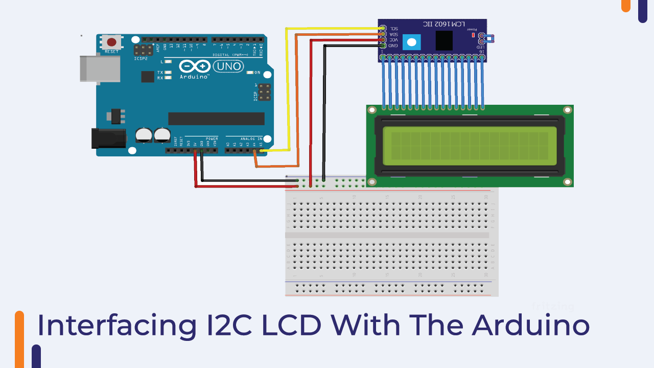
Interfacing I2C LCD With The Arduino
As discussed earlier only two pins of Arduino are required for I2C display and those pins are SCL and SDA.
You need to connect the SCL pin of the Arduino to the SCL pin of the LCD and the SDA pin of the Arduino to the SDA pin of the LCD backpack.
You can refer to the following image to understand the interfacing diagram.
Arduino Code For I2C Backpack LCD
As we are using I2C Backpack to interface LCD with Arduino, we need to establish I2C communication between LCD device and Arduino.
You can either design your own code or you can use libraries that are easily available in the market.
In my case, I have used ready-made i2cliquied_crystal.h library.
One more thing, there is a line in our code on which we are passing I2C address.
In my case the I2C address of my LCD is 0X16 but it may be different in your case.
So, if the Arduino code doesn’t work for you, don’t worry. You can follow the following procedures to resolve this issue.
Troubleshooting For I2C Backpack
If your LCD is not showing any character on it then there can be two possible reasons for this.
Wiring is not correct.
The LCD’s I2C address is different from the set address.
To resolve these problems, you must first check the wiring diagram. Make sure you have connected everything correctly. You can refer to the connection diagram to understand the connection diagram.
If the problem persists then there may be an issue with the I2C address. To resolve this issue, you must know the I2C address.
And you can use the following code to get the I2C address of your device.
This code returns the I2C address of the devices that are connected to the Arduino’s I2C communication port.
#include <Wire.h>


void setup()
{
  Wire.begin();

  Serial.begin(9600);
  while (!Serial);             // Leonardo: wait for serial monitor
  Serial.println("nI2C Scanner");
}


void loop()
{
  byte error, address;
  int nDevices;

  Serial.println("Scanning...");

  nDevices = 0;
  for(address = 1; address < 127; address++ )
  {
    // The i2c_scanner uses the return value of
    // the Write.endTransmisstion to see if
    // a device did acknowledge to the address.
    Wire.beginTransmission(address);
    error = Wire.endTransmission();

    if (error == 0)
    {
      Serial.print("I2C device found at address 0x");
      if (address<16)
        Serial.print("0");
      Serial.print(address,HEX);
      Serial.println("  !");

      nDevices++;
    }
    else if (error==4)
    {
      Serial.print("Unknown error at address 0x");
      if (address<16)
        Serial.print("0");
      Serial.println(address,HEX);
    }
  }
  if (nDevices == 0)
    Serial.println("No I2C devices foundn");
  else
    Serial.println("donen");

  delay(5000);           // wait 5 seconds for next scan
}
It was about the I2C Address Scanner code now as you know the I2C address of your display, you can use the following code for your application.
If everything is done correctly, the following code will display “Hello Robu!!” on the first line of the LCD. will display.
If it is not showing any character on the LCD then please follow the above procedure.
If the problem persists please let me know in the comment section.
#include <Wire.h>
#include <LiquidCrystal_I2C.h>

// Set the LCD address to 0x27 for a 16 chars and 2 line display
LiquidCrystal_I2C lcd(0x27, 16, 2);

void setup()
{
	// initialize the LCD
	lcd.begin();

	// Turn on the blacklight and print a message.
	lcd.backlight();
	lcd.print("Hello, world!");
}

void loop()
{
	// Do nothing here...
}
Servo Motor
In this Orange Arduino Intermediate Kit you are getting a small servo motor. These types of motors are very famous in automation fields and are being widely used in industrial applications.
The main advantage of this type of motor is that these motors are available in the market at very low cost and over that the shaft speed of such motors is very precise.
These motors come with the proper casing. If you open the cover of the motor you will see a DC motor and an encoder in it.
The encoder used in servo motor is used to control the angular moment of the shaft.
This was all about the introduction of servo motor if you want to know more about servo motor then you can use the following link to know more about servo motor.
In the below section we will learn about the interfacing of the servo motor with the Arduino.
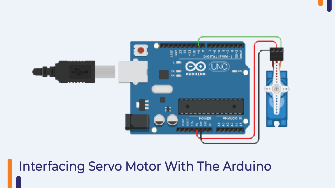
Interfacing Servo Motor With Arduino
There are three pins in any servo motor I have mentioned the function of those pins below please have a look.
VCC – 4 to 9V – Here you can connect the positive pin of the external power supply to the servo motor.
GND – Here you can connect the GND pin of the Arduino and the GND pin of the external power source.
Signal Pin – This is the signal pin of the servo motor. One end of this pin is connected to the internal microcontroller and you need to connect the other end to the GPIO pin of the Arduino.
Please check the following image.
Arduino Code For Servo Motor
In this section, I have explained the Arduino code that we will use to control the servo motor.
As discussed earlier, the servo motor has a built-in control unit that keeps track of the moment of the shaft. The signal pin is connected only to the same control unit.
When we give PWM signal to that control unit. The control unit turns on the DC motor for a specific period depending on the duration of the received PWM signals.
For example, if we give a 2ms PWM signal to the servo motor, the control unit will rotate the motor 180-degrees. When we give a PWM signal of 1ms duration to the servo motor, it will rotate the motor towards the 0-degree position.
Talking about the code, in this code we are using a servo.h library. This library is specially designed for servo motor and BLDC motor.
Work in the Code –
We are using two functions in the code and they are as follows;
- servo.attach
- servo.write
Servo.attach – This function is used to define the signal pin for servo motor. Make sure you only connect the PWM pin to this pin. If you connect the digital pin to this pin then the servo motor will not work properly.
Servo.write – This function takes one parameter and that is angle. We have to pass angle value to this pin. In the following code, we are commanding the motor to rotate 90 degrees.
It was about the code now you can use the following code and make necessary changes.
If you face any problem please let me know in the comment section.
#include <Servo.h>

int pos = 0;

Servo servo_9;

void setup()
{
  servo_9.attach(9, 500, 2500);

}

void loop()
{
  // sweep the servo from 0 to 180 degrees in steps
  // of 1 degrees
  for (pos = 0; pos <= 180; pos += 1) {
    // tell servo to go to position in variable 'pos'
    servo_9.write(pos);
    // wait 15 ms for servo to reach the position
    delay(15); // Wait for 15 millisecond(s)
  }
  for (pos = 180; pos >= 0; pos -= 1) {
    // tell servo to go to position in variable 'pos'
    servo_9.write(pos);
    // wait 15 ms for servo to reach the position
    delay(15); // Wait for 15 millisecond(s)
  }
}
Function in The Code –
We are using two functions in the code and they are as follows;
- Servo.attach
- Servo.write
Servo.attach – This function is used to define the signal pin for the servo motor. Make sure you only connect the PWM pin to this pin. If you connect the digital pin to this pin then the servo motor will not work properly.
Servo.write – This function takes one parameter and that is the angle. We have to pass the angle value to this pin. In the following code, we are commanding the motor to rotate 90 degrees.
It was about the code now you can use the following code and make necessary changes.
If you face any problems please let me know in the comment section.
Stepper Motor
As you know, stepper motor is the type of DC motor which converts the electrical pulses into step-by-step mechanical motion of the shaft.
Unlike other DC motors, this motor has a permanent magnet rotor that rotates when the stator is energized.
The construction of the stator is similar to that of a normal DC motor. The only difference is that the stator of this type of motor has mechanical teeth. After providing the pulse generated by the microcontroller to the stator, these teeth align with the teeth of the rotor.
The sequence of pulses generated by the microcontroller allows the shaft of the motor to rotate in discrete steps. This motor uses a certain amount of such pulses to complete one revolution, these pulses are also responsible for controlling the speed of the motor. Increasing the frequency of the input pulses increases the speed of rotation of the motor shaft.
The following picture shows the internal construction of the stepper motor.

Interfacing Stepper Motor With Arduino
You are getting a 28byj-48 stepper motor and UNL-2003 stepper motor driver with this Orange Arduino Intermediate Kit. This motor has four pins and you have to connect those pins to the stepper motor driver as shown in the picture.
Please check the following image and do the connection accordingly.

Arduino Code For Stepper Motor
In the following section, I have shared the code to control the stepper motor. With the help of following code we are generating a sequence. That sequence will rotate the motor in a clockwise or counterclockwise direction.
You can use the following code and watch the stepper motor rotate.
#include <Stepper.h>

const int stepsPerRevolution = 200;  // change this to fit the number of steps per revolution
// for your motor


// initialize the stepper library on pins 8 through 11:
Stepper myStepper(stepsPerRevolution, 8, 9, 10, 11);

int stepCount = 0;  // number of steps the motor has taken

void setup() {
  // nothing to do inside the setup
}

void loop() {
  // read the sensor value:
  int sensorReading = analogRead(A0);
  // map it to a range from 0 to 100:
  int motorSpeed = map(sensorReading, 0, 1023, 0, 100);
  // set the motor speed:
  if (motorSpeed > 0) {
    myStepper.setSpeed(motorSpeed);
    // step 1/100 of a revolution:
    myStepper.step(stepsPerRevolution / 100);
  }
}
As far as I know, I have covered everything about stepper motors if you have any doubts please let us know in the comments section.
DS1302 RTC Module
RTC (Real Time Clock), as the name implies, the DS1307 RTC module is used as a module to remember TIME and DATE and, as I told you earlier, it has an inbuilt battery Which keeps the RTC module running.
Because of the battery involved, the module stays on and gives accurate time information whenever asked.
Features of DS1307 RTC Module
- The real-time clock counts minutes, seconds, date, hours, month day of the week, year and leap-year compensation up to 2100.
- 318 temporary data storage RAM
- Working current of 2.0V, less than 300nA
- Read / Write clock or RAM data with two kinds of mode of single-byte transfer mode and multi-byte character set
- 8 pin DIP package or optional 8 pin SOIC package based on the surface assembly
- Simple 3 wire interface
- Compatible with TTL Vcc=5V
- Double power supply pipe for main power and backup power supply.
DS1302 RTC Module Pinout
- VCC: Module power supply – 5V
- GND: Ground
- DAT: Data pin
- RST: Reset
- CLK: Clock pin
DS1302 RTC Module Interfacing With Arduino
Please note that this module does not support I2C, it uses three-wire serial communication to communicate with the master.
In the following image, you can see the interfacing diagram of the RTC module with the Arduino.

Installing the Arduino Library
After doing the connections, we will require an Arduino Code.
But we don’t need to write the complete code from scratch because someone has already lowered our burden by writing the library for this module.
We can use that Arduino library to talk with this module.
You can refer to this Rtc library by Makuna.
Arduino Code For DS1302 RTC Module
#include <DS1302.h>
#include <Wire.h>
#include <LiquidCrystal_I2C.h>

DS1302 rtc(2, 3, 4);

LiquidCrystal_I2C lcd(0x27, 16, 2); // Here we are using 0x27 default address. If the display is not working, then try changing the I2C address.

void setup()
{

  rtc.halt(false);
  rtc.writeProtect(false);

  Serial.begin(9600);

  lcd.init();
  lcd.backlight();

  //rtc.setDOW(SUNDAY);
  //rtc.setTime(11, 32, 0);
  //rtc.setDate(12, 2, 2017);

}

void loop()
{
  Serial.print(rtc.getDOWStr());
  Serial.print(" ");

  Serial.print(rtc.getDateStr());
  Serial.print(" -- ");

  Serial.println(rtc.getTimeStr());

  lcd.clear();
  data ();
  ora ();

  delay (1000);
}

void data ()
{
  lcd.setCursor(0, 0);
  lcd.print(rtc.getDOWStr());
  lcd.print(" ");
  lcd.print(rtc.getDateStr());
}

void ora()
{
  lcd.setCursor(0, 1);
  lcd.print(rtc.getTimeStr());
}
By using the above code, you can save real-time in the module and read the exact time from the module. In this part of this blog, I will tell you how you can store time and then how you can read data from the module. But before that, let’s understand the usage of the Functions used in the code.
DS1307 rtc
Here DS1307 is the class name and “rtc” is the object we created for that class to access the data and functions of this class.
rtc.set(uint8_t sec, uint8_t min, uint8_t hour, uint8_t day, uint8_t month, uint16_t year).
The DS1307 class has a “set” method, this method is used to set TIME and DATE. Using the above line of code, we are giving the date and time to the function.
Ex: rtc.set(23, 12, 2, 19, 6, 1996)
Date- 19/06/1996(DD-MM-YYYY)
Time – 2-12-23 (HH-MM-SS)
rtc.start()
This function is used to start I2C communication with DS1307. It fetches the SEC and CH bytes from the DS1307 class.
rtc.get(uint8_t *sec, uint8_t *min, uint8_t *hour, uint8_t *day, uint8_t *month, uint16_t *year)
This function of the DS1307 class gives information related to the time and date saved in the module.
That was about the RTC Module you get with this module. If you have any doubt please let us know in the comment section.
MFRC-522 RC522 RFID
RFID is a radio identification system being widely used in the automation industry.
This technology uses RF signals to transfer information. It has three main components which are as follows.
RFID Reader –
This is a reader that reads the information of an RFID tag. This module has an inbuilt antenna and radio transmitter-receiver which receives the signal transmitted by the RFID receiver.
RFID Tags –
RFID tags are mounted on items that need to be counted. There are two types of RFID tags available in the market.
- Active RFID Tags
- Passive RFID Tag
Active RFID tags have an inbuilt battery that powers the RFID tag control unit whereas passive RFID tags do not have an inbuilt battery that receives power from the RFID readers and after receiving power it returns its information to the RFID reader.
I hope you are now clear about RFID technology. If you have any doubt you can ask me in the comment section. In the next part of this blog, we will learn about interfacing RFID cards with Arduino.
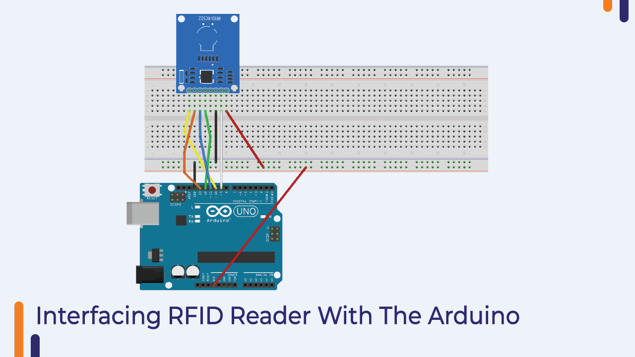
MFRC-522 RC522 RFID Interfacing With Arduino
The RFID you get with this kit uses SPI communication. SPI communication is parallel line communication and it uses four pins which are as follows.
MOSI – Master out slave in
Miso – Master in slave out
SCK – Clock line
VCC and GND – Power Pins
To interface the given RFID reader with the Arduino we will be using the Arduino’s SPI communication port and the interfacing diagram is as follows.
Arduino Code For MFRC-522 RC522 RFID
The following code is for the RFID reader if you have connected the RFID reader with the Arduino properly then you can use the following code and start working with the RFID reader.
#include <SPI.h>
#include <MFRC522.h>

#define SS_PIN 10
#define RST_PIN 9
MFRC522 mfrc522(SS_PIN, RST_PIN);

void setup()
{
  Serial.begin(9600);
  SPI.begin();
  mfrc522.PCD_Init();
  Serial.println("Approximate your card to the reader...");
  Serial.println();

}
void loop()
{

  if ( ! mfrc522.PICC_IsNewCardPresent())
  {
    return;
  }

  if ( ! mfrc522.PICC_ReadCardSerial())
  {
    return;
  }

  Serial.print("UID tag :");
  String content= "";
  byte letter;
  for (byte i = 0; i < mfrc522.uid.size; i++)
  {
     Serial.print(mfrc522.uid.uidByte[i] < 0x10 ? " 0" : " ");
     Serial.print(mfrc522.uid.uidByte[i], HEX);
     content.concat(String(mfrc522.uid.uidByte[i] < 0x10 ? " 0" : " "));
     content.concat(String(mfrc522.uid.uidByte[i], HEX));
  }
  Serial.println();
  Serial.print("Message : ");
  content.toUpperCase();
  if (content.substring(1) == "29 C2 07 5E") // Make sure you change this with your own UID number
  {
    Serial.println("Authorised access");
    Serial.println();
    delay(3000);
  }

 else   {
    Serial.println(" Access denied");
    delay(3000);
  }
}
Sound Sensor
The sound sensor is the module that is used to detect the sound signals. It has a microphone that detects the sound waves and generates an analog output according to the received frequency of the sound.
It has an inbuilt gain amplifier that is used to adjust the gain of the module. If the module is not generating the output properly then you can adjust the potentiometer to adjust the gain of the module.
In the next part of this blog, we will learn about interfacing the sensor with Arduino.
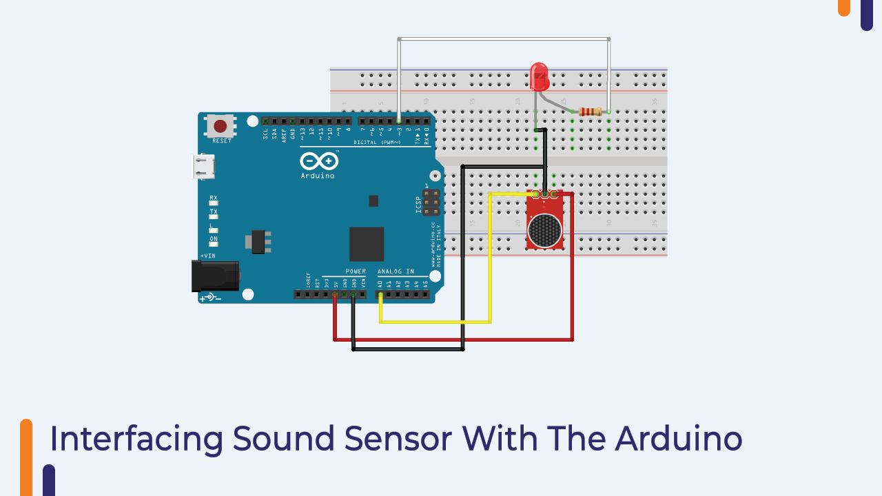
Interfacing Sound Sensor With Arduino
The sound sensor we are getting with this kit has three pins they are as follows.
Vcc – You can connect this pin to the 5v pin of the Arduino.
GND – This is the GND pin of the module. You can connect this pin to the GND pin of the Arduino.
Signal pin – Here you will get the output of the signal. The module will generate high-level signals If the audible frequency of the signal is present and if there is silence then the module will generate a LOW-level signal.
The connection diagram is so simple. I have shared the interfacing diagram below.
Arduino Code For Sound Sensor
Since the sound sensor generates a high-level signal or a low-level signal, we are using the digital read function to read the output of the sound sensor.
You can use the below code to work with this module.
int soundSensor=A0;
int LED=3;
boolean LEDStatus=false;

void setup() {
 pinMode(soundSensor,INPUT);
 pinMode(LED,OUTPUT);

}

void loop() {

  int SensorData=digitalRead(soundSensor);
  if(SensorData==1){

    if(LEDStatus==false){
        LEDStatus=true;
        digitalWrite(LED,HIGH);
    }
    else{
        LEDStatus=false;
        digitalWrite(LED,LOW);
    }
  }
 }
DHT11 Temperature And Humidity Sensor Module
If you are working on an IoT project then this sensor will help you to collect the data of the surrounding environment. This sensor also has an inbuilt capacitive temperature sensor and thermometer.
This sensor is designed in such a way that it measures humidity and temperature digitally.
Talking about its working principle, when the moisture covers the top part of the sensor, the water vapor will be absorbed by the substrate.
Then the substrate generates ions, the increase in ions will decrease the resistance between the two electrodes.
And as the resistance between the two electrodes is decreasing, we will see a change in the voltage reading. And we can calculate humidity based on variation in resistance.
Talking about the temperature sensor, the NTC type thermistor has been given in the DHT11 sensor. This thermistor is nothing but a temperature sensor.
The output value of the thermistor changes according to the change in the surrounding temperature. So by calculating the change in the output voltage of the sensor we can find out the temperature reading.
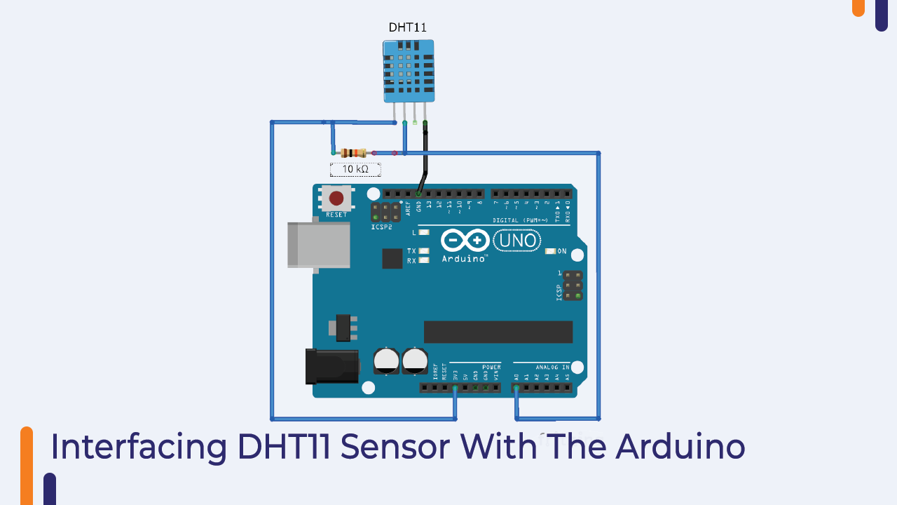
Interfacing DHT11 Sensor With Arduino
In the following section, I have shown the interfacing diagram of DHT11 sensor with Arduino.
The DHT11 sensor has three pins. You can connect those three pins to Arduino as shown in the picture below.
Arduino Code DHT11 Interfacing With Arduino
In this code, we are using DHT.h library. This library will take care of all the timing requirements and return only the required results.
Please use the following line code to work with DHT11 sensor. If you have any doubts please let us know we will be happy to assist you.
#include "DHT.h"

#define DHTPIN A0     // Digital pin connected to the DHT sensor

#define DHTTYPE DHT11   // DHT 11
//#define DHTTYPE DHT22   // DHT 22  (AM2302), AM2321
//#define DHTTYPE DHT21   // DHT 21 (AM2301)

// Connect pin 1 (on the left) of the sensor to +5V
// NOTE: If using a board with 3.3V logic like an Arduino Due connect pin 1
// to 3.3V instead of 5V!
// Connect pin 2 of the sensor to whatever your DHTPIN is
// Connect pin 4 (on the right) of the sensor to GROUND
// Connect a 10K resistor from pin 2 (data) to pin 1 (power) of the sensor

// Initialize DHT sensor.
// Note that older versions of this library took an optional third parameter to
// tweak the timings for faster processors.  This parameter is no longer needed
// as the current DHT reading algorithm adjusts itself to work on faster procs.

DHT dht(DHTPIN, DHTTYPE);

void setup() {
  Serial.begin(9600);
  Serial.println(F("DHTxx test!"));

  dht.begin();
}

void loop() {
  // Wait a few seconds between measurements.
  delay(2000);

  // Reading temperature or humidity takes about 250 milliseconds!
  // Sensor readings may also be up to 2 seconds 'old' (its a very slow sensor)
  float h = dht.readHumidity();
  // Read temperature as Celsius (the default)
  float t = dht.readTemperature();
  // Read temperature as Fahrenheit (isFahrenheit = true)
  float f = dht.readTemperature(true);

  // Check if any reads failed and exit early (to try again).
  if (isnan(h) || isnan(t) || isnan(f)) {
    Serial.println(F("Failed to read from DHT sensor!"));
    return;
  }

  // Compute heat index in Fahrenheit (the default)
  float hif = dht.computeHeatIndex(f, h);
  // Compute heat index in Celsius (isFahreheit = false)
  float hic = dht.computeHeatIndex(t, h, false);

  Serial.print(F(" Humidity: "));
  Serial.print(h);
  Serial.print(F("%  Temperature: "));
  Serial.print(t);
  Serial.print(F("C "));
  Serial.print(f);
  Serial.print(F("F  Heat index: "));
  Serial.print(hic);
  Serial.print(F("C "));
  Serial.print(hif);
  Serial.println(F("F"));
}
Water Level Sensor
This sensor works on the principle of variable resistance. The sensor consists of a series of parallel exposed conductors.
Together this series acts as a variable resistor whose resistance varies according to the water level in the water tank.
The longer the sensor is submerged in water, the better the conductivity and the lower the resistance. The less water the sensor is immersed in, the worse the conductivity and the higher the resistance.
The water level sensor is designed according to the resistance of the water produced. i.e. it will produce a voltage proportional to the resistance.
Interfacing Water Level Sensor With Arduino
This sensor has three output pins which are as follows.
S (signal pin) is an analog output which will be connected to
Arduino’s analog pin.
+VCC is the sensor’s powering pin. Accepted input voltage is 3.3v to 5v.
- The -GND bus is a ground connection.
- In this interfacing, connect the signal pin of the sensor to A0 of the Arduino.
- Then connect the VCC of the sensor to digital pin 7 of the Arduino.
- And the sensor’s GND to the Arduino’s ground.
- After that connect the cathode of RED, YELLOW, GREEN LED to digital pins 2,3,4 of Arduino respectively.
- And then connect all the anodes of the LED usually to the GND pins of the Arduino.

In this way, you can interface this sensor with Arduino.
Arduino Code For Water Level Sensor With Arduino
Once you have your circuit ready, upload the following code to your Arduino software.
To represent our threshold level there are two variables which are used as Upper Threshold and Lower Threshold.
Below the threshold level, there will be a red LED, above the threshold level there will be a green LED, in between these two levels there will be a yellow LED.
/* Change these values based on your calibration values */
int lowerThreshold = 420;
int upperThreshold = 520;

// Sensor pins
#define sensorPower 7
#define sensorPin A0

// Value for storing water level
int val = 0;

// Declare pins to which LEDs are connected
int redLED = 2;
int yellowLED = 3;
int greenLED = 4;

void setup() {
	Serial.begin(9600);
	pinMode(sensorPower, OUTPUT);
	digitalWrite(sensorPower, LOW);

	// Set LED pins as an OUTPUT
	pinMode(redLED, OUTPUT);
	pinMode(yellowLED, OUTPUT);
	pinMode(greenLED, OUTPUT);

	// Initially turn off all LEDs
	digitalWrite(redLED, LOW);
	digitalWrite(yellowLED, LOW);
	digitalWrite(greenLED, LOW);
}

void loop() {
	int level = readSensor();

	if (level == 0) {
		Serial.println("Water Level: Empty");
		digitalWrite(redLED, LOW);
		digitalWrite(yellowLED, LOW);
		digitalWrite(greenLED, LOW);
	}
	else if (level > 0 && level <= lowerThreshold) {
		Serial.println("Water Level: Low");
		digitalWrite(redLED, HIGH);
		digitalWrite(yellowLED, LOW);
		digitalWrite(greenLED, LOW);
	}
	else if (level > lowerThreshold && level <= upperThreshold) {
		Serial.println("Water Level: Medium");
		digitalWrite(redLED, LOW);
		digitalWrite(yellowLED, HIGH);
		digitalWrite(greenLED, LOW);
	}
	else if (level > upperThreshold) {
		Serial.println("Water Level: High");
		digitalWrite(redLED, LOW);
		digitalWrite(yellowLED, LOW);
		digitalWrite(greenLED, HIGH);
	}
	delay(1000);
}

//This is a function used to get the reading
int readSensor() {
	digitalWrite(sensorPower, HIGH);
	delay(10);
	val = analogRead(sensorPin);
	digitalWrite(sensorPower, LOW);
	return val;
}
8*8 Matrix Display
The display has 8 rows of 8 LEDs for a total of 64 LEDs.
There are 5 connectors on the right side and 5 connectors on the left on the back of the display. All connectors have the same symbol except for the third connector, which is marked DIN on the right, DOUT on the left.
- Meaning of connectors:
- VCC 5 volt input (+)
- GND 0 Volt Input (-) (GND = Ground)
- DIN/DOUT DIN for data entry, DOUT for data output
- CS connector for selection (CS = chip selection)
- CLK connector for synchronization signal (CLK = CLockK)
8*8 Dot Matrix Display Interfacing With Arduino
The aim of the project is to interface an Arduino Uno board with an 8 x 8 LED matrix for displaying information.
Even though this project uses a single 8 x 8 LED matrix with a compatible MAX 7219 IC, multiple LED matrices can be connected in series for a long scrolling display.
Connect the components as shown in the circuit diagram. The working of the system is as follows.

3 of the 14 available digital input/output pins are used to control the display driver IC MAX 7219.
The 3 pins on the MAX7219 IC are clock, data in and load (or cs in the case of MAX 7221 IC).
A maximum clock frequency of 10MHz can be implemented. DIN (Data In) accepts serial data from the microcontroller or Arduino board.
It is 16 bits long where the first 8 bits (D0 – D7) are for driving the columns of the LED matrix (SEG AG and DP of the MAX 7219 IC) and the next 8 bits (D8 – D15) are for driving ( MAX 7219 IC Key DIG 0-7) Rows of the LED Matrix.
The load pin (or CS or chip select pin in the case of the MAX7221 IC) carries the serial input data to its rising edge.
Another important pin on the Max 7219 is the ISET, which sets the peak current to drive all the LEDs in the segment. It is connected through a resistor (R1), called RESET. Capacitors filter out any noise in the supply.
When serial data is sent using Arduino (via a program), the serial data is converted into segments and digits to drive the columns and rows of the LED matrix. According to the data sent, the corresponding LEDs on the matrix light up and display the message.
Arduino Code For 8*8 Dot Matrix Display
In this section, we will learn about the code for Arduino. Since this display supports SPI communication, we need to establish SPI communication.
You can use the following code to work with the display.
If you have any doubt please let me know in the comment section.
// 2-dimensional array of row pin numbers:
int R[] = {2,7,A5,5,13,A4,12,A2};
// 2-dimensional array of column pin numbers:
int C[] = {6,11,10,3,A3,4,8,9};

unsigned char biglove[8][8] =     //the big "heart"
{
  0,0,0,0,0,0,0,0,
  0,1,1,0,0,1,1,0,
  1,1,1,1,1,1,1,1,
  1,1,1,1,1,1,1,1,
  1,1,1,1,1,1,1,1,
  0,1,1,1,1,1,1,0,
  0,0,1,1,1,1,0,0,
  0,0,0,1,1,0,0,0,
};

unsigned char smalllove[8][8] =      //the small "heart"
{
  0,0,0,0,0,0,0,0,
  0,0,0,0,0,0,0,0,
  0,0,1,0,0,1,0,0,
  0,1,1,1,1,1,1,0,
  0,1,1,1,1,1,1,0,
  0,0,1,1,1,1,0,0,
  0,0,0,1,1,0,0,0,
  0,0,0,0,0,0,0,0,
};

void setup()
{
   // iterate over the pins:
  for(int i = 0;i<8;i++)
  // initialize the output pins:
  {
    pinMode(R[i],OUTPUT);
    pinMode(C[i],OUTPUT);
  }
}

void loop()
{
  for(int i = 0 ; i < 100 ; i++)        //Loop display 100 times
  {
    Display(biglove);                   //Display the "Big Heart"
  }
  for(int i = 0 ; i < 50 ; i++)         //Loop display 50 times
  {
    Display(smalllove);                 //Display the "small Heart"
  }
}

void Display(unsigned char dat[8][8])
{
  for(int c = 0; c<8;c++)
  {
    digitalWrite(C[c],LOW);//use thr column
    //loop
    for(int r = 0;r<8;r++)
    {
      digitalWrite(R[r],dat[r][c]);
    }
    delay(1);
    Clear();  //Remove empty display light
  }
}

void Clear()
{
  for(int i = 0;i<8;i++)
  {
    digitalWrite(R[i],LOW);
    digitalWrite(C[i],HIGH);
  }
}
4*4 Matrix Keypad With The Arduino
Matrix keypads are the kind of keypads you see on cell phones, calculators, microwave ovens, door locks, etc. They are practically everywhere.
However, in DIY electronics you often need to navigate menus, punch in passwords, and control robots. Adding a keypad to your project will make these things easier.
The keypad you get with this kit is made of the membrane.
Talkign about the membrane keypads, these keypads are made of thin, flexible membrane material. They come in sizes like 4×3, 4×4, 4×1 etc. Despite their size, they all work the same way.
One great thing about them is that they come with an adhesive backing so you can attach it to almost anything. All you have to do is peel off the backing paper.
In the next part of this blog, we will learn about interfacing the keypad with Arduino.
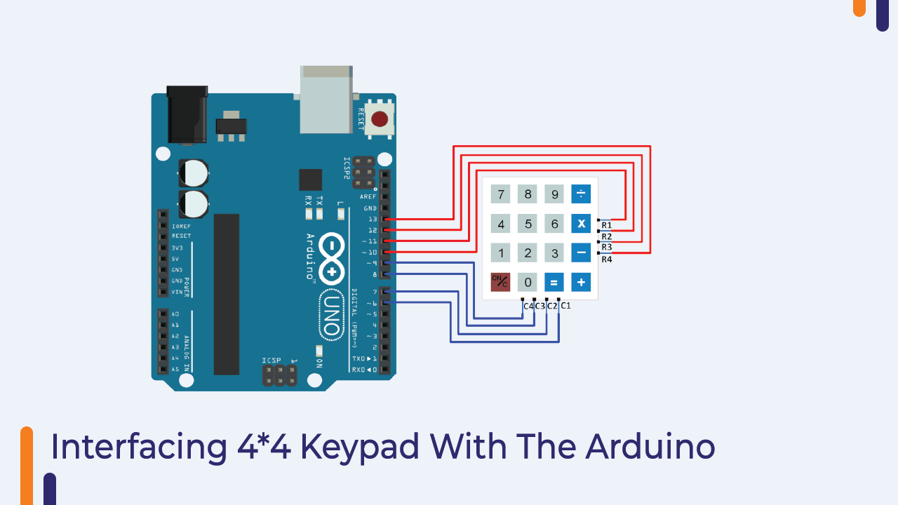
Interfacing 4*4 Matrix Display with Arduino
It is so easy to interface the matrix keypad with the Arduino. Please refer to the following image to understand the interfacing of the keypad with Arduino.
Arduino Code for 4*4 Matrix Display with Arduino
In the following section, I have shared the Arduino code for the matrix display.
In this code, we have used a library. You do not need to download this library.
It comes preinstalled with the Arduino IDE.
#include <Keypad.h>

const byte ROWS = 4; //four rows
const byte COLS = 4; //four columns

char keys[ROWS][COLS] = {
  {'1','2','3','A'},
  {'4','5','6','B'},
  {'7','8','9','C'},
  {'*','0','#','D'}
};

byte rowPins[ROWS] = {9, 8, 7, 6}; //connect to the row pinouts of the keypad
byte colPins[COLS] = {5, 4, 3, 2}; //connect to the column pinouts of the keypad

//Create an object of keypad
Keypad keypad = Keypad( makeKeymap(keys), rowPins, colPins, ROWS, COLS );

void setup(){
  Serial.begin(9600);
}

void loop(){
  char key = keypad.getKey();// Read the key

  // Print if key pressed
  if (key){
    Serial.print("Key Pressed : ");
    Serial.println(key);
  }
}
Please refer to the Libraries section in your IDE and you can use the following Arduino code.
Projects Using the Orange Arduino Intermediate Kit
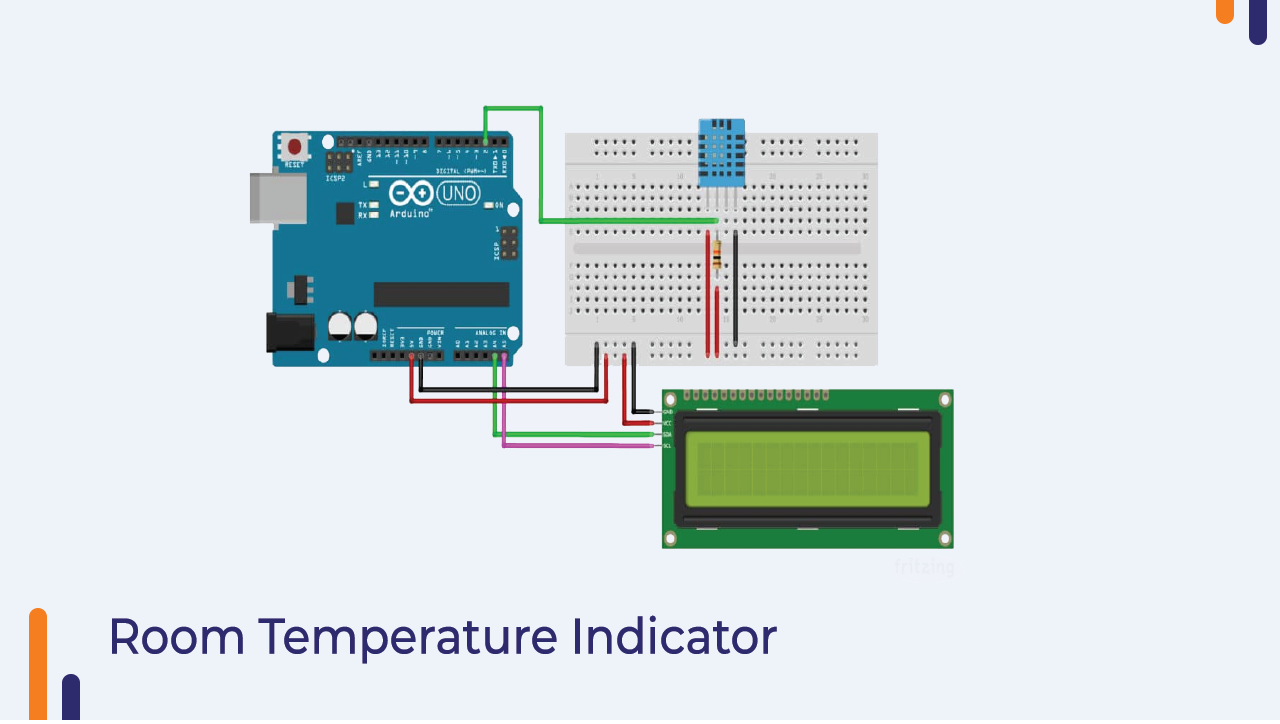
Room Temperature Indicator Using Arduino
The Room Temperature Indicator is another interesting project we can do using this Orange Arduino Intermediate Kit.
In this project, we will be using an Arduino, LCD and temperature sensor. The Arduino will read the output of the sensor and print the output to the LCD. You can use the following diagram to understand the interfacing diagram.
Arduino Code For Room Temperature Indicator
In the above code, we have integrated the code of the LCD module and DHT sensor. The Arduino is reading the output of the DHT sensor and printing to our LCD module.
#include <Adafruit_Sensor.h>
#include <DHT.h>
// Set DHT pin:
#define DHTPIN 2
// Set DHT type, uncomment whatever type you're using!
#define DHTTYPE DHT11   // DHT 11
//#define DHTTYPE DHT22   // DHT 22  (AM2302)
//#define DHTTYPE DHT21   // DHT 21 (AM2301)
// Initialize DHT sensor for normal 16mhz Arduino:
DHT dht = DHT(DHTPIN, DHTTYPE);
void setup() {
  // Begin serial communication at a baud rate of 9600:
  Serial.begin(9600);
  // Setup sensor:
  dht.begin();
}
void loop() {
  // Wait a few seconds between measurements:
  delay(2000);
  // Reading temperature or humidity takes about 250 milliseconds!
  // Sensor readings may also be up to 2 seconds 'old' (its a very slow sensor)
  // Read the humidity in %:
  float h = dht.readHumidity();
  // Read the temperature as Celsius:
  float t = dht.readTemperature();
  // Read the temperature as Fahrenheit:
  float f = dht.readTemperature(true);
  // Check if any reads failed and exit early (to try again):
  if (isnan(h) || isnan(t) || isnan(f)) {
    Serial.println("Failed to read from DHT sensor!");
    return;
  }
  // Compute heat index in Fahrenheit (default):
  float hif = dht.computeHeatIndex(f, h);
  // Compute heat index in Celsius:
  float hic = dht.computeHeatIndex(t, h, false);
  Serial.print("Humidity: ");
  Serial.print(h);
  Serial.print(" % ");
  Serial.print("Temperature: ");
  Serial.print(t);
  Serial.print(" xC2xB0");
  Serial.print("C | ");
  Serial.print(f);
  Serial.print(" xC2xB0");
  Serial.print("F ");
  Serial.print("Heat index: ");
  Serial.print(hic);
  Serial.print(" xC2xB0");
  Serial.print("C | ");
  Serial.print(hif);
  Serial.print(" xC2xB0");
  Serial.println("F");
}