
In a previous blog on the Orange 37 in 1 Sensor Kit, we discussed the types of sensors you get with this kit and how to use those sensors with Arduino.
In this blog, we will learn about the top 5 projects that can be done using this orange 37 in 1 sensor kit.
Before we start working with this kit, I would like to tell you that, you may need some additional components to complete the following project.
I have shared links to those additional products in the respective project sections. If you don’t have those products you can buy them by visiting the respective page link.
This was the introduction to this blog; In the below section we will talk about the projects that we can do with the help of this orange 37 in 1 sensor kit.
List of The Projects
- Fire Alarm System Using Arduino
- Clap Switch Project Using Arduino
- Door Monitoring System Using Reed Switch
- Arduino Weather Station
- Automated Plant Watering System Using IoT
Arduino Fire Alarm System

List of The Required Components
Nowadays fire alarm systems can be seen everywhere around us, these systems are used to detect fire situations and reduce the damage caused by fire.
Such a fire alarm system uses a flame sensor to detect a fire.
In this section, we will learn to design the Arduino Fire Alarm System. We are getting a flame sensor with an orange 37 in 1 sensor kit. That sensor we will be using to design our Arduino-based fire alarm system.
So, first let’s talk about the system designing and then we will talk about the interfacing diagram and after that we will talk about the Arduino code.
The system we are designing will be used to monitor a critical situation, so the system should detect a fire within a second and take the necessary action to reduce the damage.
So, to fulfill all these requirements, we have to choose the required components wisely.
The sensor we are getting with the orange 37 in 1 sensor can easily detect the fire/light source whose wavelength is 760nm – 1100 nm and the detection angle of this sensor is 60.
It was about the sensor now we will have to add something to our project which will notify us if there is any kind of fire. And for this, we can use a buzzer.
We are getting two type of buzzer with orange 37 in 1 sensor kit. Active type buzzer and passive type buzzer.
If you want to know the difference between these two products then we request you to visit this blog.
Blog Link
We have used active buzzer in this project.
So, it was about the components that we need to design an Arduino based fire alarm system.
These components will be connected to Arduino and Arduino will take necessary action based on the input signals received from the sensor and the code case we have written.
Interfacing Diagram For Arduino Based Fire Alarm System
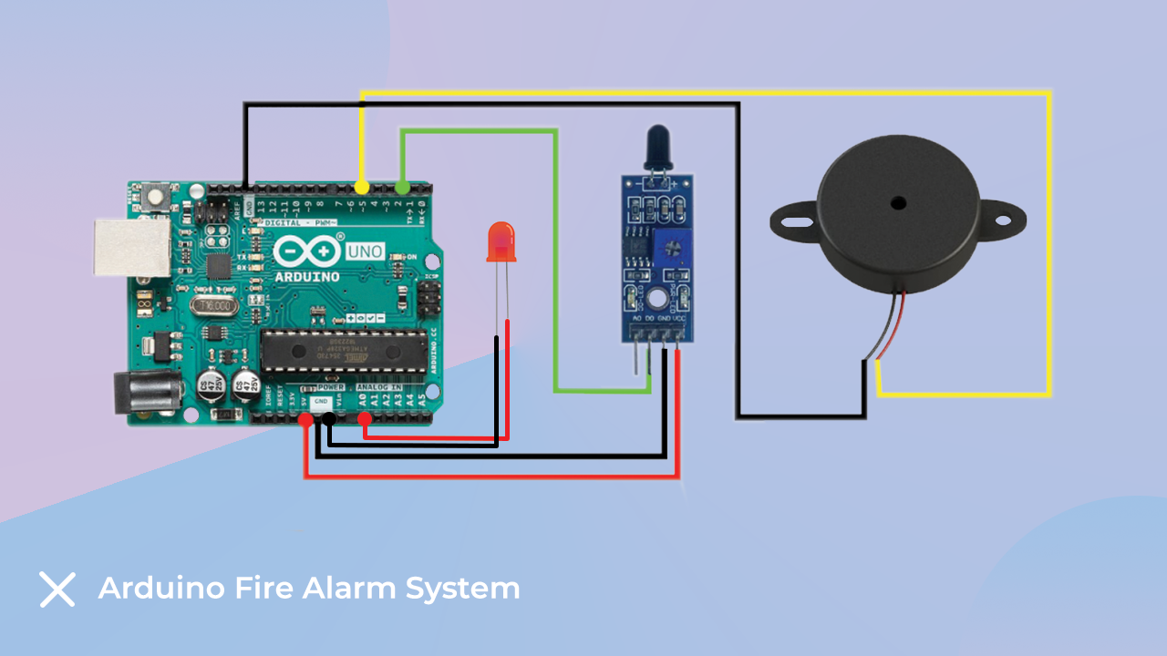
As discussed earlier, we are using Arduino UNO, flame sensor and buzzer to design an Arduino based fire alarm system.
In this section we will understand the interfacing diagram.
In the following image you can see, we have connected the flame sensor to the A0 analog pin of Arduino, and the buzzer module we have connected to the 7-number pin of Arduino.
Please Note –
- The system we are designing is not a complete system. This system will notify you only when there is a fire situation. If you want to design a complete project then you can use a single channel relay module.
- Water is used to control a fire in most fire alarm systems. So, you can add sprinkles to your project and you can connect the input of the water-pumping-motor connected to that sprinkler to that single channel relay module.
So, this was about the interfacing diagram for Arduino based fire alarm system. In the next section, we will understand the Arduino code.
Arduino Code For Arduino Based Fire Alarm System
The Arduino code that we will design will take input from the flame sensor and turn on the indicator.
The output of the flame sensor will be in analog. So, we have to use the analogRead function to read the output of the sensor.
The analogRead function will return values in the range 0 to 1024. So, we have to set a threshold to get accurate results.
In the code below, I have set a limit of 800. Therefore, when the output value of the analogRead function is crossing the set threshold value, the Arduino is turning on the buzzer. If you are using a relay module then you can also turn on the relay module at the same time.
So, these are the code cases that we have designed.
I have prepared the following logic to perform the above tasks. If you are accomplishing the above task using your own separate logic then you can use that.
    #define Fire_sensor 2
    #define Buzzer 5
    #define Light A0
    #define ldelay 500
    #define bdelay 500
    void setup() {
        Serial.begin(9600);
        pinMode(Fire_sensor, INPUT);
        pinMode(Buzzer, OUTPUT);
        pinMode(Light, OUTPUT);
    }
    void loop() {
        if (int a = digitalRead(Fire_sensor) == LOW) {
            alert();
        } else {
            digitalWrite(Buzzer, LOW);
            digitalWrite(Light, LOW);
        }
    }
    void alert() {
        digitalWrite(Light, HIGH);
        digitalWrite(Buzzer, HIGH);
        delay(ldelay);
        digitalWrite(Light, LOW);
        digitalWrite(Buzzer, LOW);
        delay(ldelay);
        digitalWrite(Light, HIGH);
        digitalWrite(Buzzer, HIGH);
        delay(ldelay);
        digitalWrite(Light, LOW);
        digitalWrite(Buzzer, LOW);
        delay(ldelay);
        digitalWrite(Light, HIGH);
        digitalWrite(Buzzer, HIGH);
        delay(ldelay);
        digitalWrite(Light, LOW);
        digitalWrite(Buzzer, LOW);
        delay(ldelay);
    }
Arduino Clap Switch Project

Have you ever thought of controlling your home appliances just by snapping your thumb? If yes then this project will help you to turn that idea into reality.
To complete this project we may need the following components.
List of Components
We would have used relay modules and controlled AC devices but doing that type of work can be risky. If proper precautions are not taken.
Therefore, if you do not have prior knowledge of electrical systems, please do not attempt to control AC appliances using the method described in this blog.
Coming back to our discussion, the purpose of the sound sensor we have used in this blog is to convert the sound signal into a digital signal.
Interfacing Diagram For Arduino Controlled Clap Switch Project
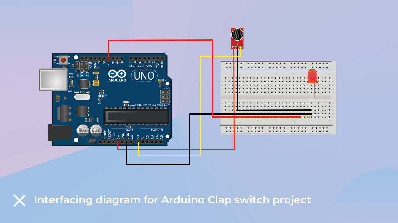
As discussed earlier, we have used sound sensor, LED and buzzer module to complete this project.
The sound sensor we have used in this project will convert an analog signal into an electrical signal and the output type of the sensor will be analog.
So, since the output type of the sensor is analog, we need to connect this sensor to the analog pin of the sensor.
In my case, I have connected the signal pin of the sensor to the A0 pin of the Arduino.
Talking about the LED, we have connected the anode pin of the LED to pin number 7 and the cathode pin of the LED to the GND pin of the Arduino.
Please refer to the following image to understand the connection diagram properly.
Arduino Code For Arduino Clap Switch Project
In this project we are turning on the LED by clapping. But how will the Arduino differentiate when you clap and when we are talking?
The answer to the above question is, the sound sensor will generate an electrical signal depending on the frequency of the surrounding signals.
The output of the sound sensor is connected to the Arduino, so we need to set a threshold value to identify the frequency of the clap sound.
When the frequency of the audio signal crosses the set threshold value, the Arduino will turn On the LED and on the next clap sound, the Arduino is turning Off the LED.
You can use similar logic of the following Arduino code or you can design your own.
Please check the below code and if you have any doubts please let me know in the comment section.
void setup() {
  Serial.begin(9600);             // using serial port to check analog value
  pinMode(2, OUTPUT);             // LED on digital pin 2
}

void loop() {
  int analog_val;                 // analog value read from A2
  static bool led_state = false;  // current state of LED

  analog_val = analogRead(A2);

  if (analog_val > 10) {          // trigger threshold
    // toggle LED
    if (led_state) {
      led_state = false;          // LED was on, now off
      digitalWrite(2, LOW);
      Serial.println(analog_val); // print analog value for debug purposes
    }
    else {
      led_state = true;
      digitalWrite(2, HIGH);      // LED was off, now on
      Serial.println(analog_val);
    }
    delay(50);  // wait for clap noise to subside
  }
}
Arduino Based Door Monitoring System Using Reed Switch

List Of The Required Projects
Arduino-based door monitoring system using reed switch is another interesting project that we can make with the help of sensor which we are getting with orange 37 in 1 sensor kit.
This project will be used to monitor the status of opening and closing of doors.
When someone will open the door, the sensor will turn on the buzzer and when the door is closed the buzzer will go Off.
We are using reed sensor to detect the position of the door opening and closing.
If you want to know more about reed sensor you can check this blog.
Reed Switch Blog- Orange 37 in 1 Sensor Kit
This was an introduction to the Arduino-based door lock monitoring system. In the next section, we will talk about the interfacing diagram for the Arduino-based door lock monitoring system.
Interfacing Diagram For The Arduino Based Door Lock System
We have used the reed switch and buzzer module for this project. In the below image you can see the interfacing diagram for Arduino based door lock system.
The reed sensor has two pins. In the following image you can see, we have connected one end of the reed switch to the 5v pin and the other end to the GPIO pin of the Arduino module.
Talking about the buzzer pin, we have connected the GND pin of the buzzer to the GND pin of the Arduino and the 5v pin of the buzzer to the 5v pin of the Arduino.
Please refer to the following image to understand the interfacing of Arduino based door lock system.

Arduino Code For Arduino Based Door Monitoring System
We are designing an Arduino based door lock system. In this system we have used reed switch.
The output type of the reed switch is digital. Hence, we are using the digitalRead function to read the output of the sensor.
When someone will open the door, we will get a digital high pulse on the Arduino pin connected to the read sensor.
In our code, we have written a condition that will continuously check the status of the reed-switch-connected pin and turn Off the LED module when the reed switch status changes.
Arduino Code Explanation
In the following Arduino code, we are reading the output of the sensor and turning on the LED.
According to the working principle of the reed switch, the reed switch acts as a closed switch when the magnet is placed near the reed switch.
When the reed switch generates a high voltage, we are reading that signal through the Arduino and turning on the LED.
Please use the below code and if you have any doubts please let us know.
const int reedPin = 8;
const int buzzer = 13;
bool switchState = HIGH;

void setup()
{
  Serial.begin(9600);
  pinMode(reedPin, INPUT);
  pinMode(buzzer, OUTPUT);
  digitalWrite(buzzer, LOW);
}

void loop()
{
 switchState = digitalRead(reedPin);
 if (switchState == LOW)
  {
    digitalWrite(buzzer, HIGH);
    Serial.println("Reed Switch is Closed. LED is ON");
  }
 else
  {
   digitalWrite(buzzer, LOW);
   Serial.println("Reed Switch is Open. LED is OFF");
  }
}
Arduino Weather Station
List of The Required Components
Arduino Weather Station is an IOT sector-related project. In this project, we are monitoring the ambient temperature and humidity and displaying the data on the LCD module.
But do you know where we can use this project? No, let me tell you.
We all use smartphones, don’t we? We get the feature of Weather Station in the smartphone. If we turn that feature on, we start receiving weather information.
We get the data of the place where we are staying, but do you think that your service provider also lives at your place? no right!! Then how do they get accurate information about your locations?
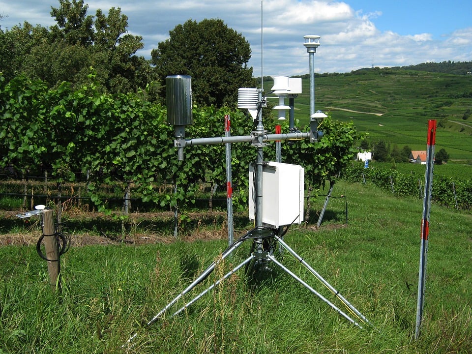
They use data from such small weather stations installed in your area.
These weather stations collect the data around you and publish this data on the internet with the help of APIs.
What is an API?

API is an application peripheral interface. As humans use words to communicate with each other in the same way the web applications use APIs to communicate with each other.
Weather stations collect information related to the surrounding weather and crate the data in JSON format. That JSON format data is then made available over the Internet.
Alike your service provider, other service provider also purchases data from these websites and publishes it on their respective applications.
And this is how you see the accurate weather data of your city in your smartphone.
There will be several types of sensors that are commonly used in weather stations. Those sensors collect all kinds of data from the surrounding environment.
As we are learning about weather stations, we have only used temperature and humidity sensors.
So, it was about the introduction of weather stations. In the next part of this blog, we will talk about the interfacing diagram of the sensor with Arduino.
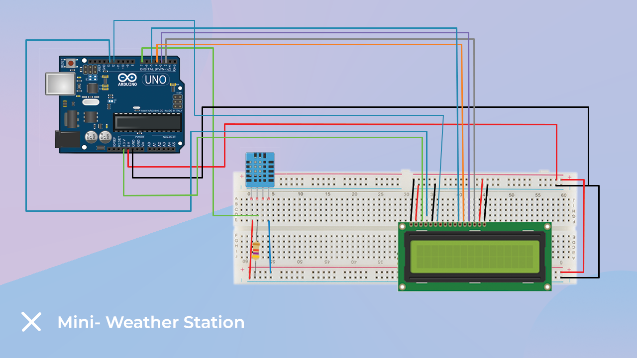
Interfacing The Temperature Sensor With The Arduino
We have used the DHT11 sensor in this project. That sensor consists of an NTC-type thermistor. This is nothing but a temperature sensor.
The output voltage of the thermistor changes according to changes in the surrounding temperature. So, by calculating the change in the output voltage of the sensor we can find out the temperature readings.
This sensor can also be used to measure humidity also. If you want to know how this sensor can be used to measure humidity you can check our following blog.
The other thing we will be using in this project is the LCD display. We are reading the output of the sensor and printing that information to the LCD screen.
You can refer to the following image to understand the interfacing of the sensor with Arduino.
Arduino Code For Weather Station
In this code, we are using the DHT.h library. This library will take care of all time requirement and return only required result.
You can download the library from here.
In our code, we have used the following functions. These functions are from the DHT.h library, they return the sensor detected humidity values and temperature values.
float h = dht.readHumidity();
float t = dht.readTemperature();
The datatype of the value returned by the above function is float. Hence, we have used float datatype to store the output.
The same output we are printing on the LCD screen.
We have made a blog on LCD interfacing. If you want to know more about it then we request you to visit the following link.
LCD Interfacing With The Arduino Blog Link
You can use the following code to test the functionality. According to me, you will not have any problem but if you face any problem then you can mention your question in the comment section.
// include the library code:
#include <LiquidCrystal.h>
#include "DHT.h"

// set the DHT Pin
#define DHTPIN 8

// initialize the library with the numbers of the interface pins
LiquidCrystal lcd(12, 11, 5, 4, 3, 2);
#define DHTTYPE DHT11
DHT dht(DHTPIN, DHTTYPE);

void setup() {
  // set up the LCD's number of columns and rows:
  lcd.begin(16, 2);
  dht.begin();

  // Print a message to the LCD.
  lcd.print("Temp:  Humidity:");
}

void loop() {
  delay(500);
  // set the cursor to column 0, line 1
  // (note: line 1 is the second row, since counting begins with 0):
  lcd.setCursor(0, 1);
  // read humidity
  float h = dht.readHumidity();
  //read temperature in Fahrenheit
  float f = dht.readTemperature(true);

  if (isnan(h) || isnan(f)) {
    lcd.print("ERROR");
    return;
  }

  lcd.print(f);
  lcd.setCursor(7,1);
  lcd.print(h);
}
IoT: Automatic Plant Watering System Using Arduino

This is another interesting IOT project that we can do using Orange 37 in 1 sensor kit.
Everyone likes to do gardening. Good gardening requires proper watering. Proper watering means, the watering process should be on time and each time the plants should be watered in sufficient quantity.
Both excess water and lack of water can harm the plant. So we have to be more curious while doing this process.
But can we automate this boring task? Can we design some kind of bot or device that will take care of these things?
Yes we can design this type of device using Arduino and some sensor.
The main objective of this project is to automate the process of watering. So, to automate the process we need to think about the following.
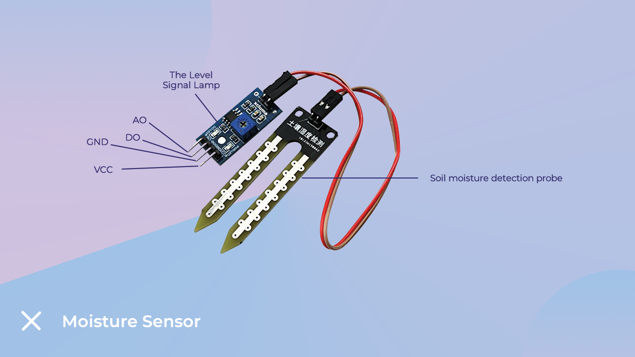
Moisture Sensor
Talking about the moisture sensor, the moisture sensor is used to detect the moisture of the soil in which the plant has been planted. The following image shows the image of the Moisture Sensor.
Time Management Unit
You can use the RTC module for time management. The RTC module uses I2C communication and is used to display applications in real-time.
RTC (Real Time Clock) As the name suggests, the DS1307 RTC module is used as a module to remember TIME and DATE and, as I told you earlier, it has an inbuilt battery which The RTC keeps the module running. Because of the battery involved, the module stays on and gives accurate time information whenever asked.
If you want to know more about RTC module then you can use following link.
The third thing we will need to complete this project is the electronic solenoid valve and a relay module.
The following image shows the image of a 12v electronic valve.
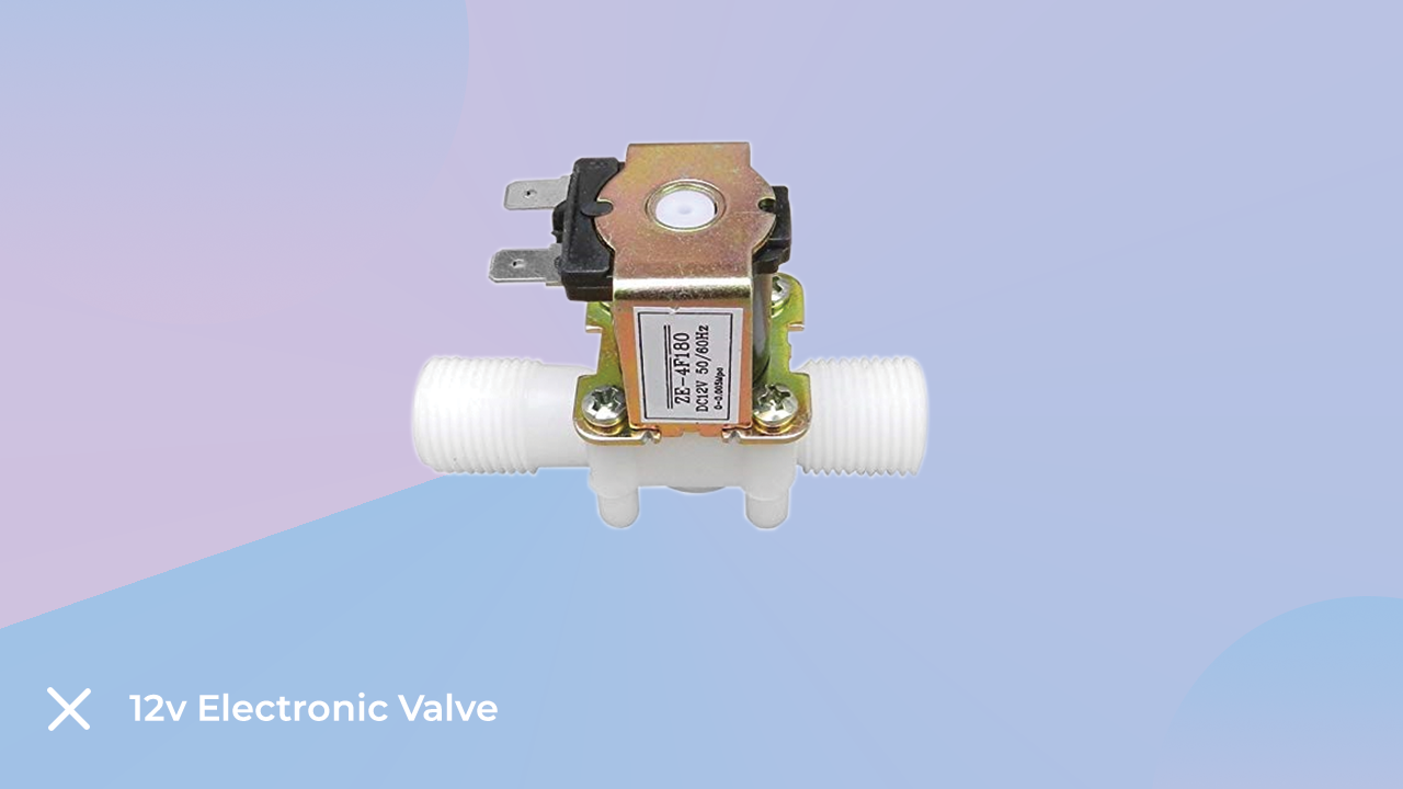
In the image above you can see that the electronic valve has two ports. One port is the inlet port and the other is the outlet port. And in the middle of those two ports, there is a circular object which is nothing but a solenoid.
When we power that solenoid, the solenoid will open the path between inlet and outlet and when we remove the power it will close that path.
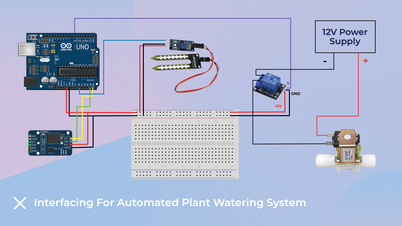
In the image below I have shown the image of the interfacing diagram of all these components please have a look and if any doubt please let me know in the comment section.
Arduino Code For Automated Plant Watering System
We can use the following code to automate the plant water system.
Before using the following code, we will understand the code-cases we need to crate and follow to complete this project.
The first thing we need to understand is that we need to set the timing of the electronic valve On and Off.
At that particular time, the electronic valve will turn on and water the plant.
After this work we have to use the moisture sensor data to monitor the moisture value of the soil.
When the soil moisture drops below a certain value we are again turning on the electromagnetic valve so that the data of the moisture sensor is very important.
So, these are the code cases that we need to design.
In the following code, I have used my logic to design an automatic Plant Watering System, but you can apply your logic if you come up with your own logic.
int solenoidPin = 4;    //This is the output pin on the Arduino we are using
#define SensorPin A0
float sensorValue = 0;


#include <Wire.h>
#include "RTCDS1307.h"

RTCDS1307 rtc(0x68);

uint8_t year, month, weekday, day, hour, minute, second;
bool period = 0;

void setup() {
  // put your setup code here, to run once:
  Serial.begin(9600);
  pinMode(solenoidPin, OUTPUT);           //Sets the pin as an output
  rtc.begin();
  rtc.setDate(19, 2, 28);
  rtc.setTime(23, 59, 50);

}

void loop() {

  // put your main code here, to run repeatedly:
  RTC_function();
  moisture_sensor();

}

void turn_on_valve()
{
    digitalWrite(solenoidPin, HIGH);    //Switch Solenoid ON
    delay(1000);                      //Wait 1 Second
}

void turn_off_valve()
{
    digitalWrite(solenoidPin, LOW);    //Switch Solenoid ON
    delay(1000);                      //Wait 1 Second
}

void RTC_function()
{
  /*get time from RTC*/
  rtc.getTime(hour, minute, second, period);
  if (!(second % 3)) rtc.setMode(1 - rtc.getMode());
  rtc.getTime(hour, minute, second, period);


  if (hour==7 && minute == 00 && second == 00)
  {
    turn_on_valve();
    delay(2000);   //You can increase the delay as per your rquirement
  }
  else if(hour==7 && minute == 00 && second == 00)
  {
     turn_on_valve();
    delay(2000);   //You can increase the delay as per your rquirement

  }
  else
  {
    turn_off_valve();
    delay(2000);   //You can increase the delay as per your rquirement

  }
}


void moisture_sensor()
{
  for (int i = 0; i <= 100; i++)
 {
   sensorValue = sensorValue + analogRead(SensorPin);
   delay(1);
 }
  sensorValue = sensorValue/100.0;
  Serial.println(sensorValue);
  if (sensorValue < 400)
  {
     turn_off_valve();
  }

  else{
        turn_off_valve();
       }
  }
Final Note
In this way, we have learned various projects that can be made using the components of this orange 37 in 1 sensor kit.
You can create many more similar projects using the components of this 37 in 1 sensor kit. Use your creative mind and start working on your ideas.
If you have any doubts about the components of this kit or would like any assistance you can contact us.