Hello and welcome to this blog, in this blog we will learn some advanced concepts of Arduino and communication protocol (Orange advance Kit).
As you already know how famous Arduino is. The use of Arduino can be seen from very small tasks to extremely high-end tasks.
These days every automation industry is choosing Arduino for their automation related projects.
And the reason Arduino is easy to use and useful for fast prototyping and this is the only reason why Arduino is being widely used in industrial applications.
We also know that there are other famous micro-controllers also available in the market but they are not designed for small size applications whereas Arduino is less expensive than those controllers.
And it’s just because of these features that Arduino has become so popular in the embedded community.
And according to me, as Arduino has become an inseparable component of our community, it is an essential skill that every embedded enthusiast should learn.
So, coming back to the discussion, in this blog we will learn about some advanced components of Arduino and understand the usage of different communication protocols of Arduino.
Talking about the components, you are getting the following components in this kit.
Component List
| Sr No. | Components Name | Quantity |
|---|---|---|
| 1. | Arduin Uno | 1 |
| 2. | Arduino Uno USB Cable | 1 |
| 3. | 65pcs Flexible Breadboard Jumper Wires | 1 |
| 4. | Switches | 6 |
| 5. | 2 Axis Joystick | 1 |
| 6. | 830 Ponits Soldless Breadboard | 1 |
| 7. | 5V 4-Phase Stepper Step Motor | 1 |
| 8. | ULN2003 Driver Board Stepper Motor Green | 2 |
| 9. | DS1302 RTC Real Time Clock Module (No Battery) | 1 |
| 10. | IR Remote Control (No Battery) | 1 |
| 11. | MFRC-522 RC522 RFID + S50 Card + Keychain | 5 |
| 12. | 1.64FT USB 2.0 A-B Male Printer Cable 0.5m | 1 |
| 13. | PS2 Game JoyStick Module | 1 |
| 14. | 1 Channel Relay 5V | 15 |
| 15. | Sound Sensor Module | 1 |
| 16. | DIP 3 Color LED Module | 1 |
| 17. | DHT11 Temperature and Humidity Sensor Module | 1 |
| 18. | Rain Water Level Detection Sensor Module | 1 |
| 19. | 0.56 inch Red 1 Digit 7 Segment LED Display 10pin | 1 |
| 20. | 0.56 inch Red 4 Digit 7 Segment LED Display 12pin | 1 |
| 21. | 8×8 Red 64 LED Dot Matrix Displays 3mm CA | 1 |
| 22. | 12x12x7.3mm Tactile Push Button Switch Square | 5 |
| 23. | Round Cap for Square Tachile Switch | 5 |
| 24. | 10K Potentiometer 15mm Shaft | 1 |
| 25. | 9V Battery Connector with DC | 1 |
| 26. | Two Layer Storage Box, size 23.416.86.2cm | 1 |
| 27. | 10 Pin Connecting Cables | 1 |
| 28. | 28mm Leg LED 5MM Red (1pcs) | 1 |
| 29. | 28mm Leg LED 5MM Green (1pcs) | 1 |
| 30. | 28mm Leg LED 5MM Yellow (1pcs) | 1 |
| 31. | 5mm 5528 LDR Light Dependent Resistor | 1 |
| 32. | 5V Active Buzzer | 1 |
| 33 | 5V passive Buzzer | 1 |
| 34 | SW-520D Vibration Sensor Metal Ball Tilt Switch | 1 |
| 35 | Resistor 1K 1/4W 1%(1pcs) | 10 |
| 36 | Resistor 10K 1/4W 1%(1pcs) | 10 |
| 37 | Resistor 220R 1/4W 1%(1pcs) | 10 |
| 38 | LM35DZ ORI. | 1 |
| 39 | 74HC595N | 1 |
| 40 | 4×4 Matrix 16 Keypad Keyboard Module 16 Button Mcu | 1 |
| 41 | 5mm 940nm Infrared Receiver LED IR Diode LED (Flame Sensor) | 1 |
| 42 | 1838B IR Receiving Head Remote Control Receiver | 1 |
So, that was about the introduction to the Orange Advance Kit, in the next part of this blog, we will learn about the interfacing and usage of these components.
2 Axis Joystick
We all used joysticks in our childhood. The kind of Super Mario games we used to play when we were kids was controlled by a joystick controller. Plus, the electronic toy cars you used to play with as a child were controlled by joysticks.
So, as you have already used the joystick, it will be very easy for you to understand the working of the joystick.
The joystick has two potentiometers. When we move the joystick, the position of the potentiometer changes.
A change in the position of the potentiometer means that the resistance of the potentiometer changes. Therefore, as the resistance is changing, the output voltage of the potentiometer also changes.
The output of those potentiometers is connected to the microcontroller. When the microcontroller receives input from those potentiometers, the microcontroller takes further necessary action based on the logic that you have added to your code.
If you want to understand the working of joystick then I request you to refer its manual. I have mentioned everything about this kit there.
<<<<<<<<Link>>>>>>>>
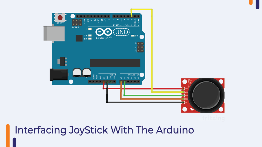
Coming back to our discussion, that joystick module has four output pins. We will discuss more about the interfacing diagram and the pin functions in the below section.
Interfacing The Joystick Module With The Arduino
You will need the following components to understand the function of the joystick.
Component List
- Arduino Board
- Connecting Cables
- Breadboard
In this section, I have explained the function of those pins in the below section, please have a look.
- X – This pin generates the analog output voltage. (0-255) and is used to monitor the movement of the joystick on the X-plane.
- Y – This pin also generates the analog output voltage and is used to monitor the movement of the joystick on the Y-plane.
- Switch – This pin is the output of the switch placed under the joystick. When we press the joystick, this pin generates high voltage. Sometimes this switch is also used to locate the Z-axis of the joystick.
Now that you know the function of each pin, we can now connect them to the Arduino.
Analog pin of module pin ‘X’ and pin ‘Y’ You can connect the analog pin of Arduino and the digital pin of the module to the digital pin of the Arduino.
Please refer to the following image to understand the connection diagram.

Arduino Code For Joystick Module
The joystick’s output is either analog or digital. Therefore, we can use analog read and digital read functions to read the output.
Since the joystick’s output is in a simple format, we don’t need to install any libraries to work with this board, the normal analog read function and digital read function will work for the application.
In the following code, we have not used any library. We have used a variable to store the value of the sensor and that value we are printing on the serial monitor using serial. print method.
It was about joystick code. If you have any doubts regarding the code then you can mention your doubts in the comment section.
#define joyX A0
#define joyY A1

int button=2;
int buttonState = 0;
int buttonState1 = 0;

void setup() {
  pinMode(7,OUTPUT);
  pinMode(button,INPUT);
  digitalWrite(button, HIGH);
  Serial.begin(9600);
}

void loop() {
 int xValue = analogRead(joyX);
 int yValue = analogRead(joyY);
 int button_output = digitalRead(button);

  Serial.print(xValue);
  Serial.print("t");
  Serial.print(yValue);
  Serial.print("t");
  Serial.println(button_output);

}
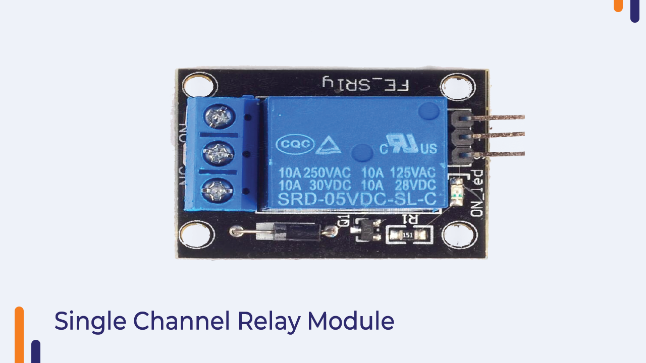
5V Single Channel Relay Module
Relay modules can be found on many electronic devices. It is an electromagnetic switch used to switch devices with high voltage requirements using low-level input signals.
In this section, we are going to understand the interfacing of relay with Arduino and understand some basics of relay module.
There are six pins in a relay module, three of those six pins are inputs and two are outputs. I have explained the function of those pins below please have a look.
Normally Open
This is the output pin of the relay module. This pin remains open till the relay module coil is energized.
NC Normally Closed
This is also an output pin. This pin remains connected to the common terminal until the relay module is activated.
Common Pin
This is an input pin.
When the relay module is powered on the normally open pin and the common terminal will connect to each other and when the relay module power is turned off the common terminal will connect to the normally closed terminal.
VCC Pin And GND Pin
These two pins are the power pins and are connected to the internal coil of the relay.
The relay module we are getting with this kit has an operating voltage of 5V for its coil.
So, we can directly connect the 5V supply to this pin.
Signal Pin
This pin is connected to the base terminal of the SMD transistor which is present on the relay module. When we give 5V to this pin, this pin will power on the relay coil.
So, it was about the introduction of the relay module. In the next part of this blog, we will understand the interfacing of the relay module.
Interfacing Relay Module with Arduino
In this section, we will learn about the interfacing of the relay module with Arduino.
As discussed earlier, there are six pins in the relay module and three of those five pins are input pins.
In the image above you can see those three pins.
You can see GND, VCC and signal pins over there.
You can connect the relay module’s GND and VCC pins to the Arduino’s VCC and GND pins and the relay module’s signal pin to any GPIO pin of the Arduino.
This was about one end of the relay module now we will understand the connections on the other side.

In the image above you can see the COM, NC and NO pins. These are connected to the load.
I hope you are clear with the connection diagram now. If you have any doubts please let us know in the comment section.
Arduino Code To Control Relay Module
In this section, we will understand the Arduino code which we will be using in the relay module.
So, the relay is connected to the Arduino and the Arduino is providing power to the relay module, so we have to use the digitalWrite function.
I have added below 200 seconds delay between execution of two tasks. The reason for adding a delay between the two functions is that if there is no delay between the relay on and off event then we will not be able to understand the difference between these two events.
So, to understand the difference between these two functions, I have used the delay function.
If you have any doubts then mention your issues in the comment section below.
int relay = 8;
volatile byte relayState = LOW;

// PIR Motion Sensor is connected to D2.
int PIRInterrupt = 2;

// Timer Variables
long lastDebounceTime = 0;
long debounceDelay = 10000;

void setup() {
  // Pin for relay module set as output
  pinMode(relay, OUTPUT);
  digitalWrite(relay, HIGH);
  // PIR motion sensor set as an input
  pinMode(PIRInterrupt, INPUT);
  // Triggers detectMotion function on rising mode to turn the relay on, if the condition is met
  attachInterrupt(digitalPinToInterrupt(PIRInterrupt), detectMotion, RISING);
  // Serial communication for debugging purposes
  Serial.begin(9600);
}

void loop() {
  // If 10 seconds have passed, the relay is turned off
  if((millis() - lastDebounceTime) > debounceDelay && relayState == HIGH){
    digitalWrite(relay, HIGH);
    relayState = LOW;
    Serial.println("OFF");
  }
  delay(50);
}

void detectMotion() {
  Serial.println("Motion");
  if(relayState == LOW){
    digitalWrite(relay, LOW);
  }
  relayState = HIGH;
  Serial.println("ON");
  lastDebounceTime = millis();
}
Ultrasonic Sensor
Ultrasonic sensors are primarily used in distance detection applications. You must have heard or used this sensor before.
If not, don’t worry, in this section of the blog, you will understand everything important about ultrasonic sensors.
We know that every sound has some frequency. We hear some frequency and some don’t. The sound frequency generated by the ultrasonic sensor is not audible to the human ear.
The ultrasonic sensor generates an ultrasonic frequency signal to detect the object. Now you must be wondering that how can an ultrasonic sensor tell the difference by generating some ultrasonic frequency?
The answer is simple, the control unit to which the ultrasonic sensor is attached uses some time-dependent logic to measure distance.
When the ultrasonic sensor is turned on, it generates some ultrasonic frequency, which frequency propagates through the air medium with known speed and velocity.
These waves form a path, which propagates through the air. When that path is obstructed by an object, ultrasonic signals travel from that point back to the receiver. They do not penetrate the object like electromagnetic waves. The returning signals are then captured by the receiver part of the ultrasonic sensor.
These signals are then passed to the control unit where the control unit calculates the output of the sensor and returns the distance.
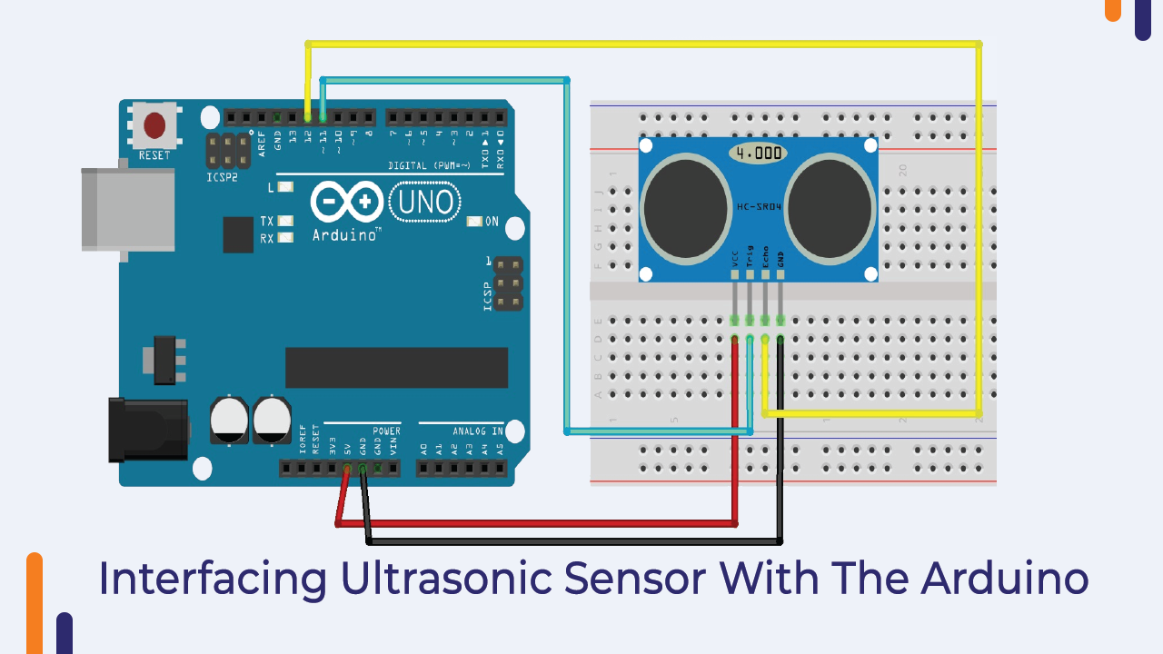
Interfacing Ultrasonic Sensor With Arduino
The HC-SR04 ultrasonic module has 4 pins, Ground, VCC, Trig and Echo.
The module’s Ground and VCC pins should be connected to Ground and to the 5 Volt pins on the Arduino board and the Trigger and Echo pins to any digital I/O pins on the Arduino board.
Please refer to the following image to understand the interfacing of ultrasonic sensor with Arduino.
Arduino Code For Ultrasonic Sensor
As we are now ready with the circuit diagram, we can move on to the coding part of the experiment.
The ultrasonic sensor generates a digital pulse on its echo pin and according to the datasheet, we need to add a 200ms delay after each successful reading of the pulse.
Please refer to the following Arduino code and if you any doubt please let us know in the comment section.
const int trigPin = 11;
const int echoPin = 12;
// defines variables
long duration;
int distance;
void setup() {
pinMode(trigPin, OUTPUT); // Sets the trigPin as an Output
pinMode(echoPin, INPUT); // Sets the echoPin as an Input
Serial.begin(9600); // Starts the serial communication
}
void loop() {
// Clears the trigPin
digitalWrite(trigPin, LOW);
delayMicroseconds(2);
// Sets the trigPin on HIGH state for 10 micro seconds
digitalWrite(trigPin, HIGH);
delayMicroseconds(10);
digitalWrite(trigPin, LOW);
// Reads the echoPin, returns the sound wave travel time in microseconds
duration = pulseIn(echoPin, HIGH);
// Calculating the distance
distance= duration*0.034/2;
// Prints the distance on the Serial Monitor
Serial.print("Distance: ");
Serial.println(distance);
}
PIR Sensor
Unlike an active infrared sensor, a passive IR sensor does not require a separate transmitter and a receiver. Such IR sensors capture the ambient heat and detect the object based on the deflection in the readings.
These sensors are mainly used in home surveillance applications.
Apart from all these basics, if you examine the module, you will see two potentiometers on the PIR sensor.
A potentiometer designated as the sensitivity is used to adjust the sensing range. And a potentiometer designated as output-timing is used to adjust the delay.
Troubleshoot If The PIR Module Still Doesn’t Work
There can be many reasons in which a module may stop working and I have listed some of them below.
The module is not giving any output in the first minute after turning it on
If you’re having this problem, don’t worry, it’s not a problem, in the first minute after power is applied, the PIR sensor starts reading the IR rays around it. So let it remain stable in its surroundings.
The Output Is Not Stable
If you’re having this problem, don’t worry, it’s not a problem, in the first minute after power is applied, the PIR sensor starts reading the IR rays around it. So let it remain fixed in its surroundings.
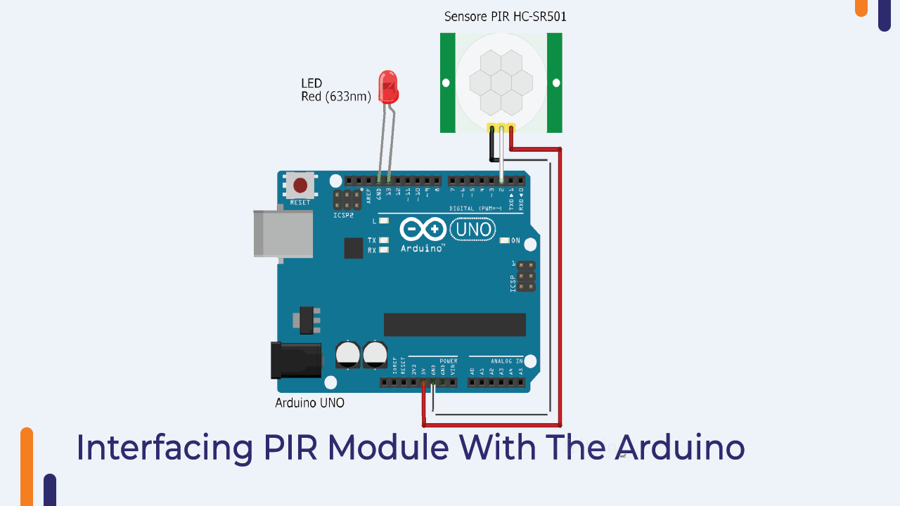
Interfacing PIR Sensor With Arduino
The following figure shows the interface of the PIR sensor with the Arduino board. In this we connected the signal pin of the PIR sensor to the digital pin of the Arduino board and powered the sensor through the Arduino itself.
Arduino Code For PIR Sensor
The following code, you can use for PIR sensor. In this code, we are using the digitalRead function to read the output of the sensor and printing the output on the serial Monitor.
If you have any doubts then please let us know in the comment section.
#define pirPin 2
int calibrationTime = 30;
long unsigned int lowIn;
long unsigned int pause = 5000;
boolean lockLow = true;
boolean takeLowTime;
int PIRValue = 0;

void setup() {
   Serial.begin(9600);
   pinMode(pirPin, INPUT);
}

void loop() {
   PIRSensor();
}

void PIRSensor() {
   if(digitalRead(pirPin) == HIGH) {
      if(lockLow) {
         PIRValue = 1;
         lockLow = false;
         Serial.println("Motion detected.");
         delay(50);
      }
      takeLowTime = true;
   }
   if(digitalRead(pirPin) == LOW) {
      if(takeLowTime){
         lowIn = millis();takeLowTime = false;
      }
      if(!lockLow && millis() - lowIn > pause) {
         PIRValue = 0;
         lockLow = true;
         Serial.println("Motion ended.");
         delay(50);
      }
   }
}
DC Motor
In this section, we will talk about DC motors. DC motors are available in different sizes in the market.
The usage of these motors also varies based on the size and load handling capability.
This motor converts electrical energy into mechanical energy. The speed of a DC motor can be controlled by applying various DC voltages; Whereas the direction of rotation of the motor can be changed by reversing the direction of the input current.
As we know that variation in voltage can be achieved with the help of PWM technology but we also know that Arduino cannot provide the required current to the motor.
Since the Arduino can only generate up to 0.50mamp of current on its GPIO pins.
And that is why we have to use an external device to control the motor.
Usually, we use motor drivers to control DC motors. And motor drivers are nothing but DC to DC converters and these DC to DC converters use transistors to control the switching actions.
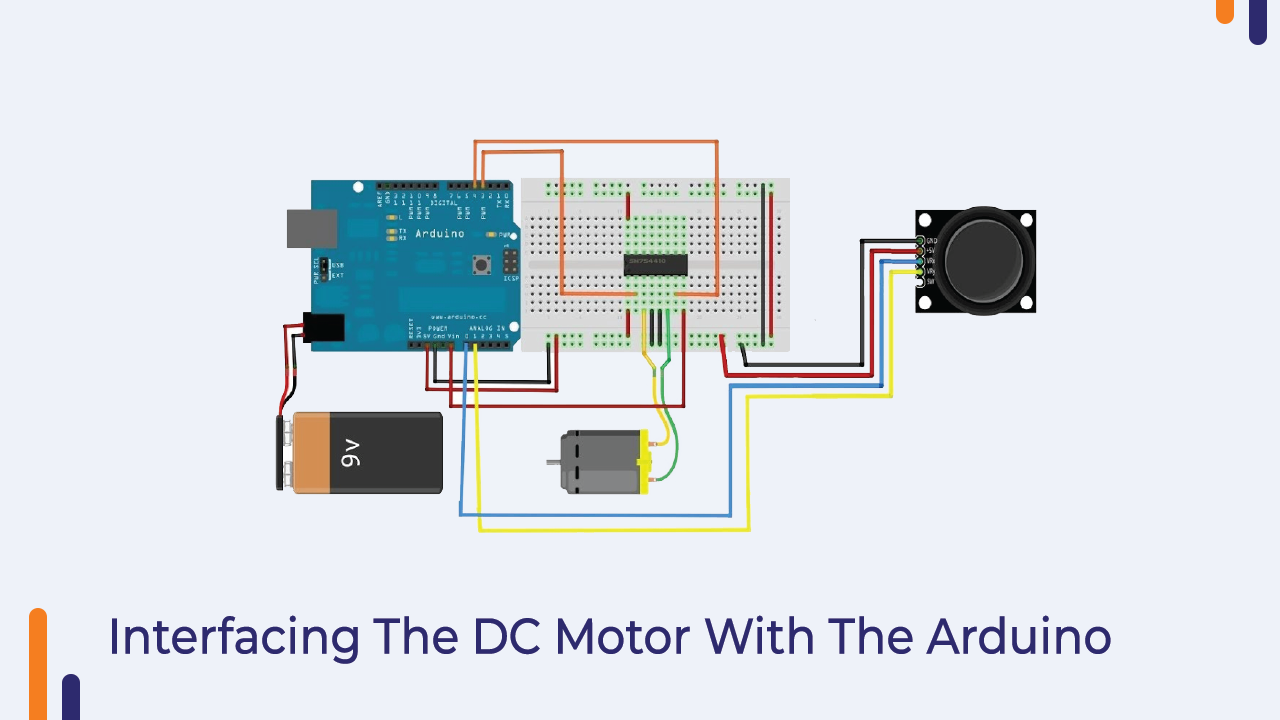
Since our application is small, we are not going to use a motor driver, but we will be using a single transistor to control the DC motor.
In the following image, I have shown the simplest way to connect the transistor to Arduino and DC Motor. Please have a look and if you have any doubts please let us know.

Arduino Code For Controlling DC Motor
In the following code, we are using PWM technology to control a DC motor. Please see the following code. If you have any problem please let us know in the comment section.
int motorPin = A0;

void setup() {
   pinMode(motorPin, OUTPUT);
   Serial.begin(9600);
   while (! Serial);
   Serial.println("Speed 0 to 255");
}

void loop() {
   if (Serial.available()) {
      int speed = Serial.parseInt();
      if (speed >= 0 && speed <= 255) {
         analogWrite(motorPin, speed);
      }
   }
}
Gyro Sensor
Nowadays, the use of Gyro sensor can be seen in many applications.
This module is a three in one pack. You get the accelerometer, gyro and temperature sensor on a single chip.
Talking about the accuracy of the module, the module uses a 16-bit analog to digital converter. As higher bit ADCs have been used, the accuracy of the module produces more accurate signals.
In the next part of this blog, we will discuss the interfacing of the module with Arduino.
Interfacing Gyro Sensor With Arduino
The gyro sensor supports two communication protocols. I2C communication protocol and SPI communication protocol.
By default, this module is configured in I2C communication, but if you want to use this module using SPI communication, you have to change the values of resistors.
Please check the datasheet of the module to understand the module requirement.
In the following image, I have shown the interfacing of the module with the Arduino.
In the below image we are using I2C communication protocol to interface MPU module with Arduino.
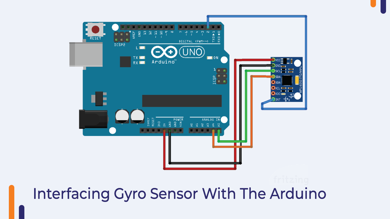
Pin Configuration
VCC and GND pins:- These pins are the power pins and are used to power the module.
SDA:- This pin is used for data transfer.
SCL:- This is the clock pin.
XDA:- External SDA
XCL:- External SCL
ADO:- I2C Slave Address LSB (Not applicable in our case)
INT:- Interrupt pin.
Arduino Code For Gyro Sensor
As we know, the sensor works on I2C communication protocol and hence, to work on this module, we need to install this MPU6050 library.
We can write our own code and use this sensor but it will not be an easy task to write complete I2C communication protocol code and use in our code.
So using a library is the best option for this application.
This will save us time and the code will also be less complicated.
Please use the following code and if there are any doubts then please let us know.
#include "I2Cdev.h"
#include "MPU6050.h"

// Arduino Wire library is required if I2Cdev I2CDEV_ARDUINO_WIRE implementation
// is used in I2Cdev.h
#if I2CDEV_IMPLEMENTATION == I2CDEV_ARDUINO_WIRE
    #include "Wire.h"
#endif

// class default I2C address is 0x68
// specific I2C addresses may be passed as a parameter here
// AD0 low = 0x68 (default for InvenSense evaluation board)
// AD0 high = 0x69
MPU6050 accelgyro;
//MPU6050 accelgyro(0x69); // <-- use for AD0 high

int16_t ax, ay, az;
int16_t gx, gy, gz;


// uncomment "OUTPUT_READABLE_ACCELGYRO" if you want to see a tab-separated
// list of the accel X/Y/Z and then gyro X/Y/Z values in decimal. Easy to read,
// not so easy to parse, and slow(er) over UART.
#define OUTPUT_READABLE_ACCELGYRO

// uncomment "OUTPUT_BINARY_ACCELGYRO" to send all 6 axes of data as 16-bit
// binary, one right after the other. This is very fast (as fast as possible
// without compression or data loss), and easy to parse, but impossible to read
// for a human.
//#define OUTPUT_BINARY_ACCELGYRO


#define LED_PIN 13
bool blinkState = false;

void setup() {
    // join I2C bus (I2Cdev library doesn't do this automatically)
    #if I2CDEV_IMPLEMENTATION == I2CDEV_ARDUINO_WIRE
        Wire.begin();
    #elif I2CDEV_IMPLEMENTATION == I2CDEV_BUILTIN_FASTWIRE
        Fastwire::setup(400, true);
    #endif

    // initialize serial communication
    // (38400 chosen because it works as well at 8MHz as it does at 16MHz, but
    // it's really up to you depending on your project)
    Serial.begin(38400);

    // initialize device
    Serial.println("Initializing I2C devices...");
    accelgyro.initialize();

    // verify connection
    Serial.println("Testing device connections...");
    Serial.println(accelgyro.testConnection() ? "MPU6050 connection successful" : "MPU6050 connection failed");

    // configure Arduino LED pin for output
    pinMode(LED_PIN, OUTPUT);
}

void loop() {
    // read raw accel/gyro measurements from device
    accelgyro.getMotion6(&ax, &ay, &az, &gx, &gy, &gz);

    // these methods (and a few others) are also available
    //accelgyro.getAcceleration(&ax, &ay, &az);
    //accelgyro.getRotation(&gx, &gy, &gz);

    #ifdef OUTPUT_READABLE_ACCELGYRO
        // display tab-separated accel/gyro x/y/z values
        Serial.print("a/g:t");
        Serial.print(ax); Serial.print("t");
        Serial.print(ay); Serial.print("t");
        Serial.print(az); Serial.print("t");
        Serial.print(gx); Serial.print("t");
        Serial.print(gy); Serial.print("t");
        Serial.println(gz);
    #endif

    #ifdef OUTPUT_BINARY_ACCELGYRO
        Serial.write((uint8_t)(ax >> 8)); Serial.write((uint8_t)(ax & 0xFF));
        Serial.write((uint8_t)(ay >> 8)); Serial.write((uint8_t)(ay & 0xFF));
        Serial.write((uint8_t)(az >> 8)); Serial.write((uint8_t)(az & 0xFF));
        Serial.write((uint8_t)(gx >> 8)); Serial.write((uint8_t)(gx & 0xFF));
        Serial.write((uint8_t)(gy >> 8)); Serial.write((uint8_t)(gy & 0xFF));
        Serial.write((uint8_t)(gz >> 8)); Serial.write((uint8_t)(gz & 0xFF));
    #endif

    // blink LED to indicate activity
    blinkState = !blinkState;
    digitalWrite(LED_PIN, blinkState);
}
ESP01 Module
ESP01 module is a WIFI module. This module is used to connect the microcontroller to the WiFi router.
ESP-01 modules are widely used in IoT applications. With the help of this module, you will be able to do a lot of things like creating data servers, creating IoT projects and what not.
If you are working on IoT project then this module should be your first choice.
How To Interface ESP01 With Arduino?
By this point, we learned about the importance of the ESP-01 module. In this section, we will understand the interfacing of esp01 module with Arduino.
This module uses UART communication for data transfer.
Therefore, we have to establish UART communication to communicate with this module.
In the below section, I have explained the pin details and shown the interfacing diagram. Please take a look
Pin Description of ESP8266 ESP-01 Module
ESP0-01–VCC: This is the power pin.
ESP-01–GND: This is the ground pin.
TX: This pin is used to transmit serial data to another device.
RX: The RX pin is used to receive serial data from other devices.
ESP0-01–RST: This is the reset pin and it is an active low pin. (The ESP8266 will reset if the RST pin receives a LOW signal).
CH_PD: This is the chip enable pin and it is an active high pin. It is usually connected to 3.3V.
GPIO0: The GPIO0 (General Purpose I/O) pin has dual functions – one for normal GPIO operation and the other for enabling the programming mode of ESP8266.
• GPIO2: This is the GPIO pin.
Please see the image below to understand the interface of ESP01 with Arduino.

Arduino Code To Control ESP01 Module
In order to work with this module, we will have to install the ESP8266.h library.
To install the board and Library follow the following steps.
- Open Arduino and then open the Preferences window.
- Enter https://arduino.esp8266.com/stable/package_esp8266com_index.json into the File>Preferences>Additional Boards Manager URLs field of the Arduino IDE. You can add multiple URLs, separating them with commas.
- Open Boards Manager from Tools > Board menu and install esp8266 platform (and don’t forget to select your ESP8266 board from Tools > Board menu after installation).
- After this you can use the code that are written in the library.
The following code will collect the information of nearby WIFI modules and will print that information on the serial monitor.
#include <ESP8266WiFi.h>

const char* ssid     = "your-ssid";
const char* password = "your-password";

const char* host = "data.sparkfun.com";
const char* streamId   = "....................";
const char* privateKey = "....................";

void setup() {
  Serial.begin(115200);
  delay(10);

  // We start by connecting to a WiFi network

  Serial.println();
  Serial.println();
  Serial.print("Connecting to ");
  Serial.println(ssid);

  WiFi.begin(ssid, password);

  while (WiFi.status() != WL_CONNECTED) {
    delay(500);
    Serial.print(".");
  }

  Serial.println("");
  Serial.println("WiFi connected");
  Serial.println("IP address: ");
  Serial.println(WiFi.localIP());
}

int value = 0;

void loop() {
  delay(5000);
  ++value;

  Serial.print("connecting to ");
  Serial.println(host);

  // Use WiFiClient class to create TCP connections
  WiFiClient client;
  const int httpPort = 80;
  if (!client.connect(host, httpPort)) {
    Serial.println("connection failed");
    return;
  }

  // We now create a URI for the request
  String url = "/input/";
  url += streamId;
  url += "?private_key=";
  url += privateKey;
  url += "&value=";
  url += value;

  Serial.print("Requesting URL: ");
  Serial.println(url);

  // This will send the request to the server
  client.print(String("GET ") + url + " HTTP/1.1rn" +
               "Host: " + host + "rn" +
               "Connection: closernrn");
  unsigned long timeout = millis();
  while (client.available() == 0) {
    if (millis() - timeout > 5000) {
      Serial.println(">>> Client Timeout !");
      client.stop();
      return;
    }
  }

  // Read all the lines of the reply from server and print them to Serial
  while(client.available()){
    String line = client.readStringUntil('r');
    Serial.print(line);
  }

  Serial.println();
  Serial.println("closing connection");
}
Project
DC Motor Speed Control Using Joystick
In this project, we are controlling the speed of the motor with the help of a joystick. We have already discussed about working of the DC motor and joystick, in this section, we will learn how to use the joystick to control the DC motor.
Talking about the interfacing details, we have already discussed about it in the above sections.
You can refer to the above section to understand the working of the DC motor and joystick with Arduino
Connection Details And Code Explanation
In this project, we are reading input from the joystick and based on the output received from the joystick we are generating the PWM signals on the pin to which NPN transistor is connected.
Please refer to the Following Image.
You can refer to the following code to understand the working of this project:
Final words – Orange advance Kit:
In this way, we learned about the components to be found with this Orange Advance kit and I am confident that the information I have shared with you will help you learn the kit.
If you have any doubts please let us know in the comment section.